Purging system and purging method for the interior of a portable type hermetically sealed container

a hermetically sealed container and purging system technology, applied in the direction of positive displacement liquid engines, liquid handling, packaging goods types, etc., can solve the problems of deterioration of the seal member, difficult to accurately keep the pressure constant in the interior or the like of the container, and difficult to stabilize the pressure, so as to achieve the effect of suppressing the flow rate and high gas purity

Active Publication Date: 2008-04-22
TDK CORPARATION
View PDF38 Cites 28 Cited by
  • Summary
  • Abstract
  • Description
  • Claims
  • Application Information

AI Technical Summary

Benefits of technology

[0012]The present invention has been made in view of the above-noted situation and has as its object to provide a purging system or a purging method which can reduce a pressure fluctuation in a space in the interior or the like of a container to thereby keep the inside pressure thereof substantially constant and prevent the deterioration of a seal member or the outflow of a gas from a seal portion resulting from the pressure fluctuation.
[0016]In the present invention, the supply amount of a gas such as an inert gas introduced into the interior or the like of a portable type hermetically sealed container and the exhaust amount of the gas exhausted from the interior or the like of the container are adjusted in conformity with pressure in the interior or the like of the container. Thereby, a pressure fluctuation fine or at short time intervals in the interior of the portable type hermetically sealed container is reduced to a very slight one, and the execution of a purging operation in a state in which the pressure is kept at substantially constant pressure is made possible. Accordingly, the possibility that the deterioration of the seal member and the outflow or the like of the gas from the seal portion which have been found out by the applicant may occur becomes null.
[0017]Also, according to the present invention, the purging operation is divided into a flushing operation and a maintaining operation, and in the flushing operation, the exhaust of the gas in the interior of the container is achieved at a great flow rate, and after most of the gas in the interior of the container has been purged, as the maintaining operation, the exhaust of the gas in the interior of the container is achieved at a relatively small flow rate, thereby achieving the higher purity of the gas enclosed in the interior of the container after the purge. Therefore, as compared with an ordinary purging operation, there is obtained the effect of suppressing the flow rate of the gas required of the purging operation to a low level.

Problems solved by technology

This phenomenon often poses a problem in subjecting the substrates, etc. to some processing and therefore, the interior of the aforementioned hermetically sealed container is usually filled with an inert gas such as nitrogen of high purity, and contains and keeps the substrates, etc. in this state.
Accordingly, when the outflow of an inert gas or the like is controlled by the opening and closing of a valve, it seems to be difficult to accurately keep the pressure in the interior or the like of the container constant.
Also, even if the intake valve is interchanged with a pressure reducing valve capable of adjusting pressure, pressure adjustment is basically effected by the opening and closing of an inert gas introduction valve, and it seems to be difficult to stabilize the pressure.
This fine pressure fluctuation occurring at short time intervals gives an unnecessary load to a seal member used to connect the interior of the container and the space in the purging system together as a hermetically sealed space, and may cause the deterioration of the seal member.
Also, when the pressure fluctuation becomes extremely great, this seal member becomes incapable of completely keep a hermetically sealing state, and this may cause the leakage of the inert gas from the seal portion.
Also, it is conceivable as a possibility that with the pressure fluctuation, vibration is given to substrates, etc. held in the interior of the container to thereby produce unexpected dust or the like.

Method used


Image

  • Purging system and purging method for the interior of a portable type hermetically sealed container
  • Purging system and purging method for the interior of a portable type hermetically sealed container
  • Purging system and purging method for the interior of a portable type hermetically sealed container

Examples


Embodiment Construction

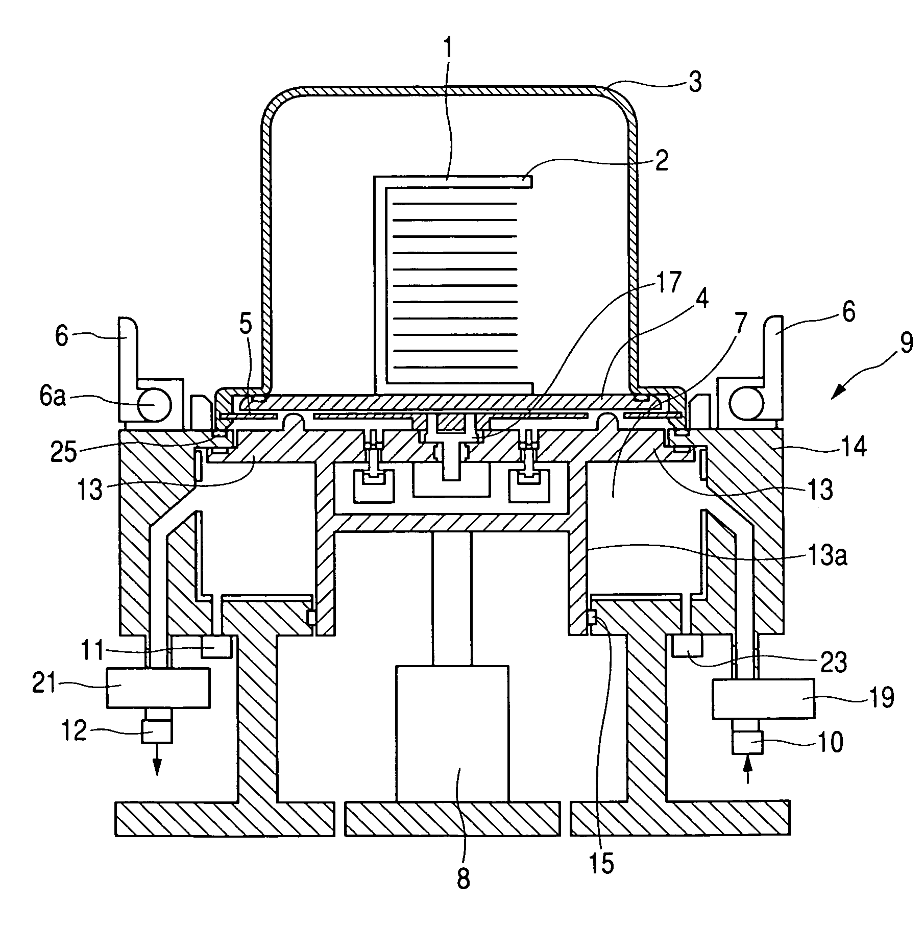
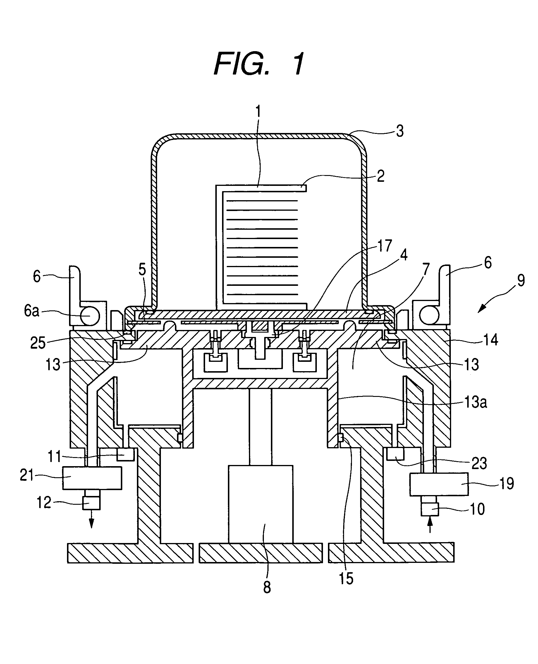
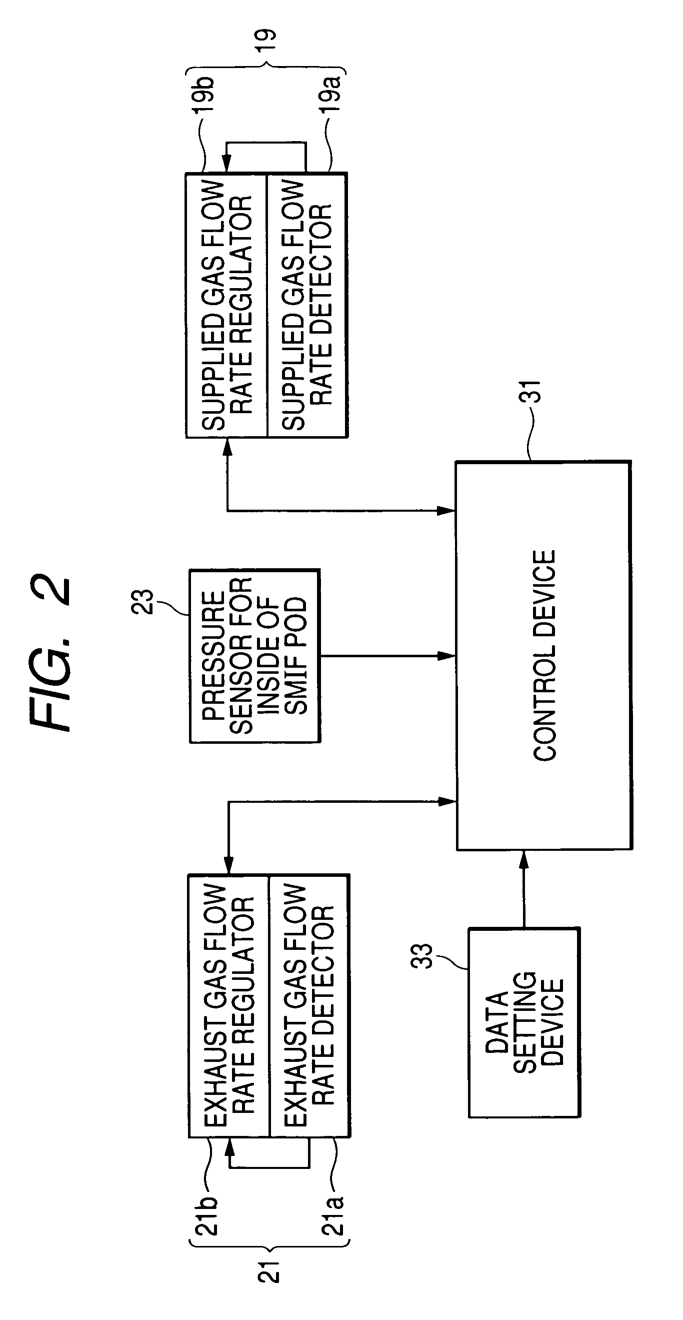
[0022]A purging system according to the present invention has as a requisite construction a purging chamber communicating with the interior of a portable type hermetically sealed container to thereby form a hermetically sealed space when the portable type hermetically sealed container is opened. This purging chamber has mounted therein a gas supplying system capable of supplying a predetermined gas to the hermetically sealed space while controlling the flow rate thereof when it communicates with the hermetically sealed space, a gas exhaust system capable of exhausting the gas present in the hermetically sealed space while controlling the flow rate thereof, and a pressure measuring apparatus communicating with the purging chamber for measuring pressure in the hermetically sealed space. The gas supplying system, the gas exhaust system and the pressure measuring apparatus are connected together through a control device, to thereby enable the flow rate of the predetermined gas supplied ...


PUM

PropertyMeasurementUnit
supply flow rateaaaaaaaaaa
exhaust flow rateaaaaaaaaaa
pressureaaaaaaaaaa

Abstract

A fine pressure fluctuation at short time intervals occurring when a portable type hermetically sealed container is purged is reduced to thereby prevent the deterioration or the like of a seal member due to the pressure fluctuation. In order to achieve this object, a gas flow rate regulating apparatus is disposed in a gas supplying system in a purging system, and pressure in the portable type hermetically sealed container during purge is measured and the result thereof is fed back to thereby control the flow rate of a supplied gas.

Description

BACKGROUND OF THE INVENTION[0001]1. Field of the Invention[0002]This invention relates to a purging system and a purging method for use when purging the interior of a space in a portable type hermetically sealed container, and more particularly to a portable type hermetically sealed container such as an SMIF pod which is a portable type hermetically sealed container for use when conveying a reticle or the like, for example, in the manufacturing process of a semiconductor or the like, and to a purging system for and a purging method of carrying out the process of purging the interior of a container such as the SMIF pod.[0003]2. Related Background Art[0004]Silicon wafers, glass substrates for liquid crystal display, substrates for hard disks, reticles, etc. are usually kept in a portable type hermetically sealed container, and are transported between processing apparatuses in manufacturing processes conforming to respective purposes while being kept in the hermetically sealed containe...

Claims


Application Information

Patent Timeline
Patent Type & Authority Patents(United States)
IPC IPC(8): B65B31/02B65B31/04H01L21/677H01L21/00H01L21/673
CPCH01L21/67017H01L21/67389H01L21/67393
Inventor MIYAJIMA, TOSHIHIKOKAGAYA, TAKESHISUZUKI, HITOSHISASAKI, MUTSUO
Owner TDK CORPARATION
Why Eureka
Try Eureka