Multi-outlet medical dispensing device

a medical and multi-outlet technology, applied in the direction of intravenous devices, suction devices, infusion syringes, etc., can solve the problems of significant risks, risk to both health professionals and patients, and the possibility of fatality of air or gas injection to patients

Inactive Publication Date: 2008-04-22
VASOGEN IRELAND LTD
View PDF3 Cites 75 Cited by
  • Summary
  • Abstract
  • Description
  • Claims
  • Application Information

AI Technical Summary

Benefits of technology

[0009]In an embodiment of the invention, a one-way valve is disposed within a housing in the second outlet for exchange of gaseous materials from the cavity of the elongate body to the environment. Preferably, the one-way valve disposed within the housing is a duckbill valve. In a preferred form of the invention, a hydrophobic membrane is disposed between the one-way valve and the cavity of the elongate body to prevent liquid from traveling from the cavity to the one-way valve. The hydrophobic membrane may be integral with the one-way valve, and disposed proximal to the cavity of the elongate body.
[0010]In a preferred embodiment of this aspect of the invention, the aforementioned third outlet for exchange of gaseous materials from the environment to the cavity suitably includes a housing in which is disposed a one-way valve. Preferably, the one-way valve is an umbrella valve. A filter is preferably disposed between the one-way valve and the environment to prevent entry of bacteria, viruses, or other materials which would compromise the sterility of the contents of the medical dispensing device. The filter may be disposed between the one-way valve and the cavity of the elongate body and suitably has the additional property of being hydrophobic to prevent liquid from traveling from the cavity to the one-way valve. Preferably, a filter and a hydrophobic membrane are separately disposed in series, between the one-way valve and the cavity of the elongate body, with the hydrophobic membrane facing the cavity. The filter is suitably disposed between the environment and the one-way valve and the hydrophobic membrane is disposed between the one-way valve and the cavity.
[0012]Suitably, the end housing has a male luer portion having complementary fit with a female luer portion of a medical accessory. When a medical accessory with a female luer portion, such as a needle, is inserted onto the male luer portion, the bottom surface of the needle abuts against the top surface of the actuating member arms to cause rearward movement of the actuating members and consequently the resilient member and the valve head are moved rearwardly as well. There is thus fluid communication through the tubular member, valve stem, and to the cavity.
[0015]There may also be a two-way valve disposed within a housing in the second outlet for exchange of gaseous materials between the environment and the cavity. Preferably, the two-way valve is a combination valve having a duckbill valve portion and umbrella valve portion with the umbrella valve portion being proximal to the cavity and having an integral membrane having hydrophobic properties and filter properties to prevent entry of bacteria, viruses, or other materials which would compromise the sterility of the contents of the medical dispensing device. In yet another aspect, a filter is disposed distal to the duckbill valve portion to prevent entry of bacteria, viruses, or other materials which would compromise the sterility of the contents of the medical dispensing device, and a hydrophobic membrane is disposed between the umbrella valve portion and the cavity to prevent liquid from traveling from the cavity to the two-way valve. In a further aspect, the filter and the hydrophobic membrane are disposed in series between the umbrella valve portion and the cavity, with the hydrophobic membrane being proximal to the cavity. Hydrophobic membrane is disposed between the one-way valve and the cavity.

Problems solved by technology

Syringes are commonly used medical dispensing devices but there are risks to both the health professional and the patient in using these common devices.
Although there have been a number of developments over the years, significant risks still remain.
The reason for this is that it is potentially fatal to inject a patient with air or gas since the gas bubble will form an embolism in the patient with likely serious, and possibly fatal, consequences.
If a needle is placed at the end of the syringe and the action of the plunger is not controlled well, it is possible that the liquid can be expelled for a considerable distance.
As can be seen, there is some loss of the medicine or biological fluid, with obvious risks for contaminating others with the material in the syringe.

Method used


Image

  • Multi-outlet medical dispensing device
  • Multi-outlet medical dispensing device
  • Multi-outlet medical dispensing device

Examples


Embodiment Construction

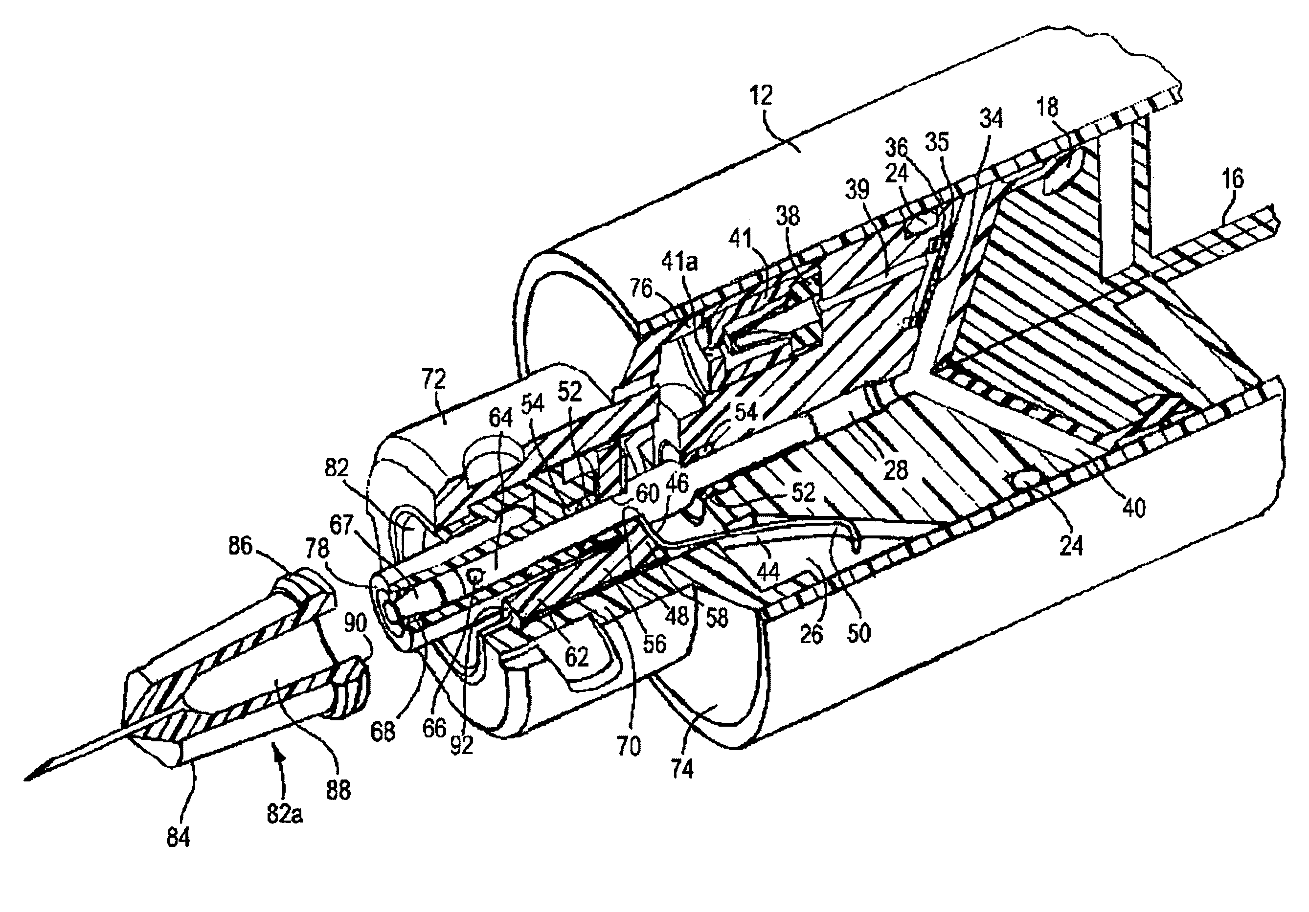
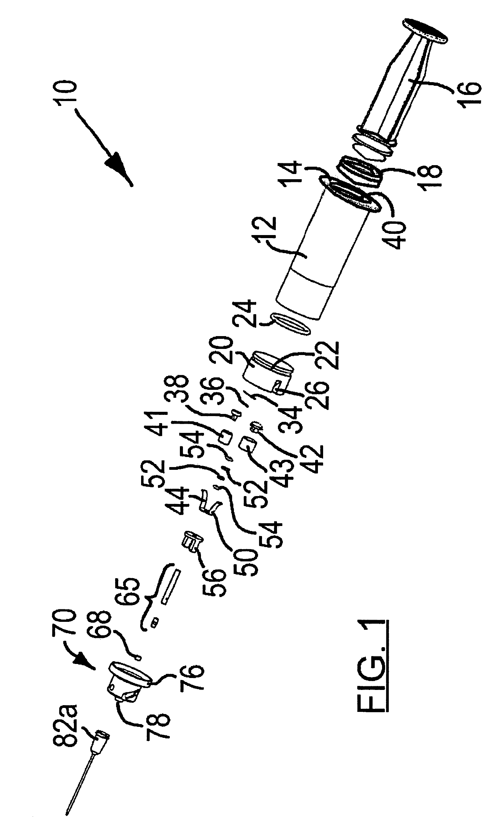
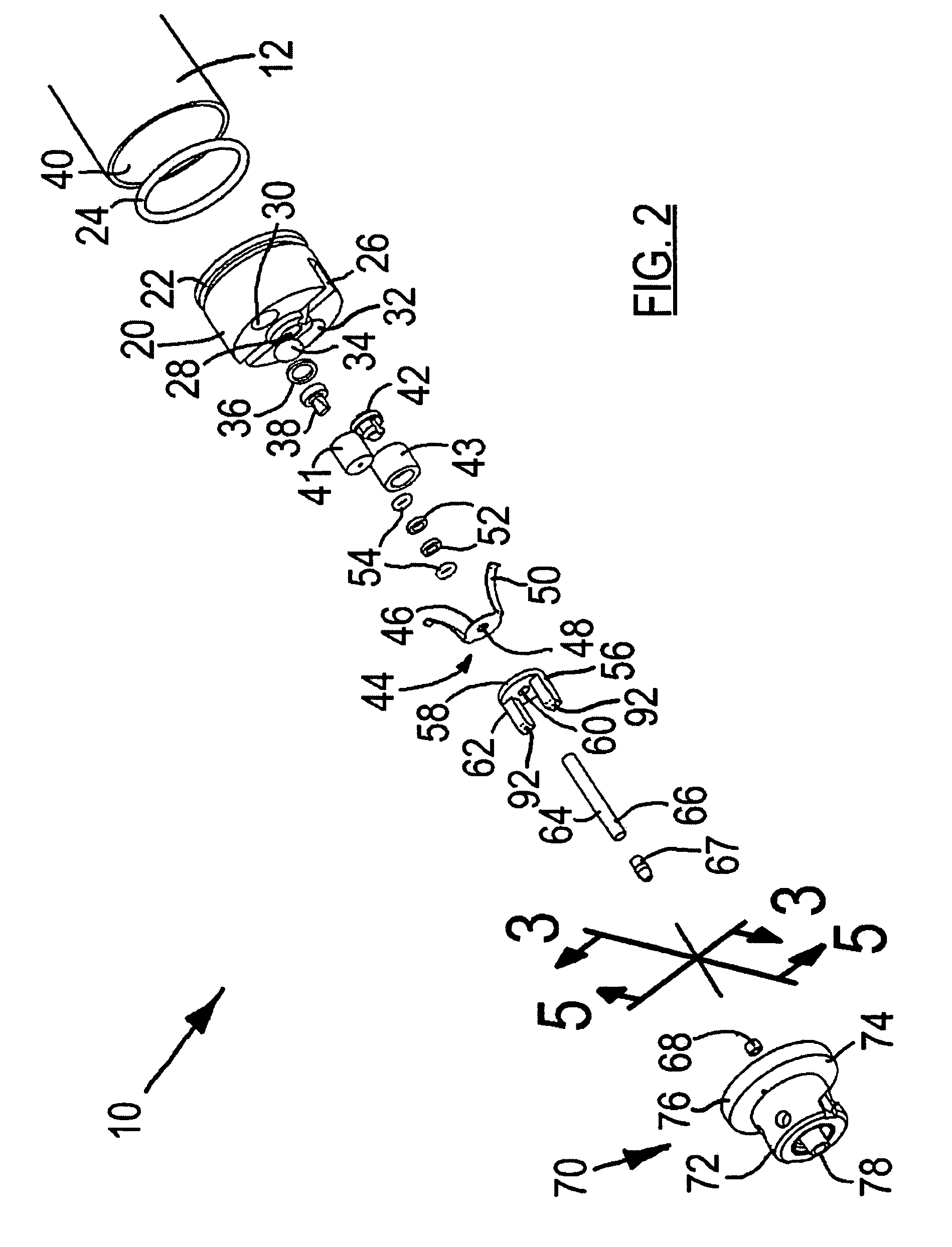
[0023]FIG. 1 shows generally, in exploded view, the medical dispensing device of the preferred embodiment of the present invention. Syringe 10 has an elongate, cylindrical, hollow body 12 having outwardly extending flanges 14 at one end as finger grips. Plunger 16 has an elastomeric head 18 attached at one end of plunger 16. Elastomeric head 18 provides sliding and sealing engagement with the inner surface of body 12. A cylindrical housing 20 having a circumferential groove 22 for placement of O-ring 24 for watertight sealing is placed in the front end of body 12. Housing 20 has inwardly and upwardly extending slots 26, a central bore 28 (as seen in FIG. 2), and bores 30 and 32 adjacent to central bore 28.

[0024]A hydrophobic membrane 34 is located in a slot 35 (see FIG. 3) on the side of housing 20 facing cavity 40 and is associated with washer 36 and a duckbill valve 38 to provide one-way flow of gaseous material from the cavity 40 of body 12, by way of a passageway 39, through duc...


PUM


Abstract

A medical delivery device comprising an elongate body having a plunger slidably and sealingly engaged to form a cavity to receive fluid materials and a first outlet disposed at an end of said body and has a male luer end portion and a valve assembly is disposed within the first outlet. The valve assembly has a valve means movable between an open position and a closed position and biasing means for biasing the valve means to a closed position. Actuating means are disposed within the male luer end portion and coupled to the valve means such that the valve means is movable to an open position when a female luer end portion of a medical accessory is coupled with the male luer end portion. A second outlet is disposed at the same end as the first outlet for controlling the exchange of gases from the environment to said cavity under the action of the plunger. Lastly, a third outlet is disposed at the same end as the first outlet for controlling the exchange of gases from the cavity to the environment under the action of the plunger.

Description

TECHNICAL FIELD[0001]The present invention relates to medical dispensing devices for dispensing medical or biological liquids by injection or other forms such as, for example, syringes and catheters.BACKGROUND ART[0002]A major concern of health professionals is the safe handling of biological materials and medicines. Syringes are commonly used medical dispensing devices but there are risks to both the health professional and the patient in using these common devices. Although there have been a number of developments over the years, significant risks still remain.[0003]When syringes are filled with biological fluids or medicines, it is usually necessary to remove any gaseous materials remaining in the body of the syringe prior to injection into the patient. The reason for this is that it is potentially fatal to inject a patient with air or gas since the gas bubble will form an embolism in the patient with likely serious, and possibly fatal, consequences.[0004]The usual procedure for ...

Claims


Application Information

Patent Timeline
Patent Type & Authority Patents(United States)
IPC IPC(8): A61M5/315A61M1/00A61M5/178A61M5/28A61M5/31A61M39/26
CPCA61M5/178A61M5/28A61M5/285A61M5/3134A61M2005/3123A61M2005/3128A61M39/26A61M2039/268
Inventor SIMPSON, PHILIP J.MATSUURA, DAVID G.GILLESPIE, WALTER D.TRINCHERA, JAMES A.COSTA, MARK P.WORONA, TARASCHEN, HAOKANBERGS, DAVID A. R.CHANCELLOR-MADDISON, KATHLEENZHAO, ROYLIM, BERNARD C. B.
Owner VASOGEN IRELAND LTD
Why Eureka
Try Eureka