Method of driving image display, driving device for image display, and image display

a technology of driving device and image display, which is applied in the direction of electric digital data processing, instruments, computing, etc., can solve the problems of high power consumption of tone voltage producing circuit, use of conventional pulse width modulation drive, and high cost of tone voltage production circuit. , to achieve the effect of good multiple tones and limited power consumption

Inactive Publication Date: 2008-04-22
SHARP KK
View PDF25 Cites 14 Cited by
  • Summary
  • Abstract
  • Description
  • Claims
  • Application Information

AI Technical Summary

Benefits of technology

[0034]Conceived in view of the foregoing problems, the present invention has an objective to offer a method of driving an image display, a driving device for an ima

Problems solved by technology

A problem arises here that the tone voltage producing circuit consumes electric power.
Additional power consumption for tone voltage production as is

Method used


Image

  • Method of driving image display, driving device for image display, and image display
  • Method of driving image display, driving device for image display, and image display
  • Method of driving image display, driving device for image display, and image display

Examples


embodiment 1

[0086]The following will describe an embodiment of the present invention in reference to figures.

[0087]A driving device for an image display in accordance with the present embodiment applies voltages to, and hence drives, pixels in a liquid crystal display (TFT-LCD), so that an image is displayed. The present invention is by no means limited to the present embodiment and applicable to displays which control the display of tones through pixel application voltage values.

[0088]Schematically, an image display 1 in accordance with the present embodiment, as shown in FIG. 18, contains a liquid crystal panel 2, a controller CTL, a power source REG, a scan line driving section GD, and a signal line driving section SD.

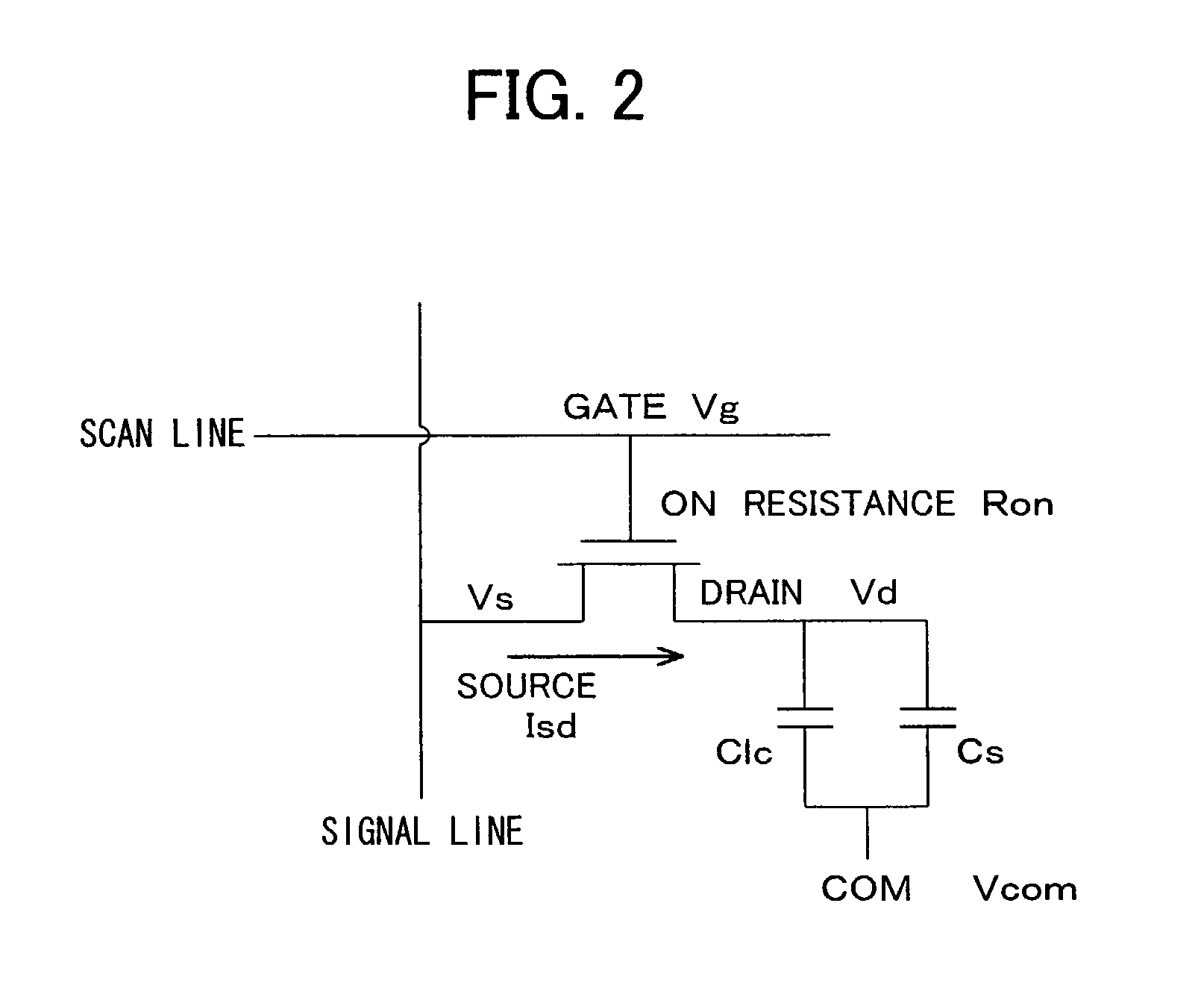
[0089]FIG. 2 is a circuit diagram of a pixel (unit pixel) in a liquid crystal panel 2 of the liquid crystal display. In the liquid crystal display, such unit pixels are provided in a matrix form across the panel.

[0090]FIG. 2 also shows part of a driving device for an image disp...

embodiment 2

[0133]The following will describe another embodiment of the present invention in reference to figures.

[0134]A driving device for an image display in accordance with the present embodiment has a similar arrangement to that of the driving device for an image display set forth in embodiment 1. Further, an image display in accordance with the present embodiment has a similar arrangement to that of the image display set forth in embodiment 1. The present embodiment differs from embodiment 1 in timings of temporal changes of the scan line voltage, the signal line voltage, and the common voltage. The following will describe these differences.

[0135]Now, the operation of the driving device for an image display in accordance with the present embodiment in the arrangement will be described in reference to figures.

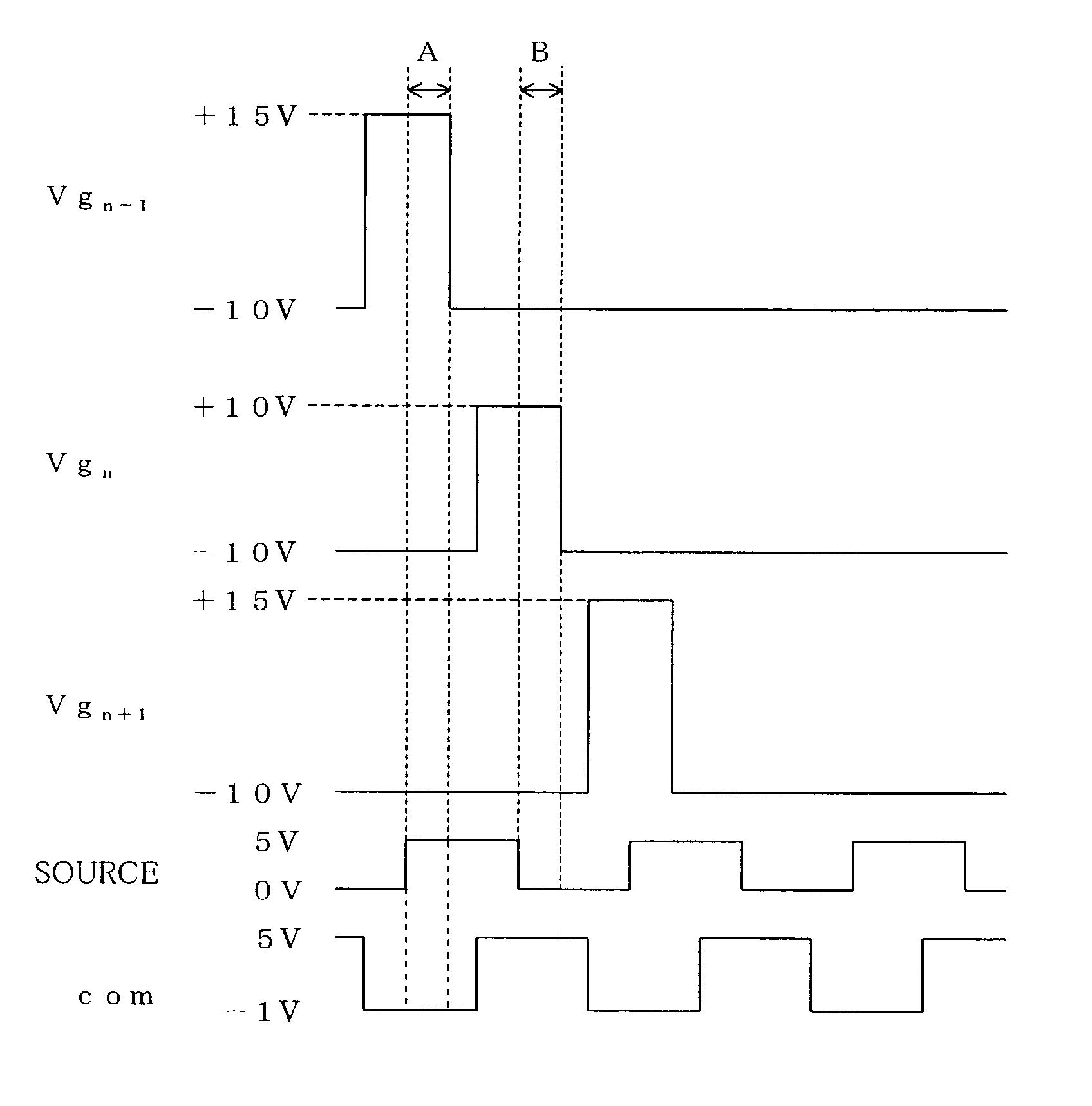
[0136]FIG. 6 is a timing chart showing temporal changes of the scan line voltage, the signal line voltage, and the common voltage, where “Vgn” and “Vgn+1” indicate scan line voltages ...

embodiment 3

[0161]The following will describe another embodiment of the present invention in reference to figures.

[0162]A driving device for an image display in accordance with the present embodiment has a similar arrangement to that of the driving device for an image display set forth in embodiment 1. Further, an image display in accordance with the present embodiment has a similar arrangement to that of the image display set forth in embodiment 1. The present embodiment differs from embodiment 1 in timings of temporal changes of the scan line voltage, the signal line voltage, and the common voltage. The following will describe these differences.

[0163]Now, the operation of the driving device for an image display in accordance with the present embodiment in the arrangement will be described in reference to figures.

[0164]FIG. 7 is a timing chart showing temporal changes of the scan line voltage, the signal line voltage, and the common voltage, where “Vgn” and “Vgn+1” indicate scan line voltages ...


PUM


Abstract

An image display according to the present invention includes a driving device which performs pulse width modulation drive, restrains power consumption, and produces a good multi-tone display. The image display makes the difference between the scan line voltage and the signal line voltage equal in positive polarity writing and negative polarity writing by which pixels are AC driven, so as to make the on-resistances of transistors equal. This allows a maximum pulse width, the size of switching elements, etc. to be determined first so that they match positive polarity writing in which the resistances value of the switching elements rise. No high frequency clock is required to produce subtle differences of charge ratio in negative polarity writing in which the resistances of the switching elements fall. Power consumption which depends on the clock frequency drops too.

Description

FIELD OF THE INVENTION[0001]The present invention relates to a method of driving an image display, a driving device for an image display, and an image display, in particular, to a method of driving an image display, a driving device for an image display, and an image display whereby an image is displayed by controlling a voltage written to a pixel electrode through adjustment of an application time of a signal line voltage applied to a signal line while a pixel switching element is in on state.BACKGROUND OF THE INVENTION[0002]Conventionally, image displays, such as active matrix liquid crystal displays using thin film transistors (TFTs) as pixel switching elements (hereinafter, “switching elements”), are in widespread use: the liquid crystal display (TFT-LCD) is an example. The liquid crystal display (LCD) in recent years has also found applications in personal digital assistants (PDAs), mobile phones, and like devices.[0003]A conventional liquid crystal display is made up of pixel ...

Claims


Application Information

Patent Timeline
IPC IPC(8): G09G5/00G09G3/20G02F1/133G09G3/36
CPCG09G3/3614G09G3/3685G09G3/3648G09G3/2014G09G2330/021G09G2300/08G09G3/36
Inventor KUMADA, KOUJIOHTA, TAKASHIGEKAGAWA, HARUHITO
Owner SHARP KK
Why Eureka
Try Eureka