Optical branching unit

a branching unit and optical technology, applied in the field of optical branching units, can solve the problems of difficult to completely prevent displacement between the axial lines of the optical waveguide, and achieve the effects of reducing light emission, reducing loss, and high wavelength uniform loss

Inactive Publication Date: 2008-04-22
ORMON CORP
View PDF15 Cites 2 Cited by
  • Summary
  • Abstract
  • Description
  • Claims
  • Application Information

AI Technical Summary

Benefits of technology

[0010]It is an object of the present invention to provide an optical branching unit, which is capable of decreasing emission of light to an output end of a branching destination after the light is branched by an optical branching unit, capable of decreasing a loss, and has a high wavelength uniformity of loss in the output side, even if displacement occurs between an input waveguide to input a light beam from the outside of a substrate and an optical transmission member outside a substrate.
[0016]Namely, according to the above-mentioned optical branching unit, emission of a multimode component to an output end of a branching destination after being branched by a branch structure is decreased, when displacement occurs between an input waveguide to input a light beam from the outside of a holding substrate to hold an optical branch structure and an optical transmission structure outside the substrate, and variations in the wavelength uniformity of loss are compensated in the output side. Therefore, the wavelength uniformity of loss is increased in each branching destination.
[0019]Namely, in an optical branching unit which branches an input light from the outside of a substrate at a predetermined branching ratio, and emits the light to the outside of a substrate, the cross section at a predetermined position between the input waveguide and optical branch is a rectangle or a non-circle with a different vertical-to-horizontal ratio, including an area that the length along the surface of a substrate is defined to be shorter than the length in the direction orthogonal to the surface of a substrate; and the cross section at the output end of each output waveguide is a rectangle or a non-circle with a different vertical-to-horizontal ratio, where the length along the surface of a substrate is defined to be longer than the length in the direction orthogonal to the surface of a substrate. Therefore, emission of a multimode component to an output end of a branching destination after being branched by the optical branching unit is decreased, when an axis displacement occurs between an input waveguide to input a light beam from the outside of a substrate and an optical transmission member outside the substrate, and variations in the output wavelength uniformity are compensated in an output side. Therefore, the wavelength uniformity of loss is increased in each branching destination.
[0028]Namely, in the above-mentioned optical branching unit, an optical waveguide which connects an optical branching unit to input a light beam from the outside of a substrate, to a plurality of optical branching unit provided among a plurality of output waveguide provided to emit a light beam divided into several beams to the outside of a substrate, includes at least an area that the length in the direction orthogonal to the surface of a substrate is defined longer than the length along the surface direction. When several stages of optical branching unit are arranged in series, it is possible to compensate variations in the wavelength uniformity of a light beam emitted to the output end to emit a light beam to the outside of a substrate. Therefore, the wavelength uniformity of loss is increased in each branching destination, and a loss of the whole branching unit is decreased.

Problems solved by technology

In many cases, an input waveguide is glued to an optical fiber, and it is difficult to completely prevent displacement between the waveguide axial line and the optical fiber center axis, during gluing the waveguide and optical fiber or hardening the glue.

Method used


Image

  • Optical branching unit
  • Optical branching unit
  • Optical branching unit

Examples


Embodiment Construction

[0038]Hereinafter embodiments of the invention will be explained in detail with reference to the accompanying drawings.

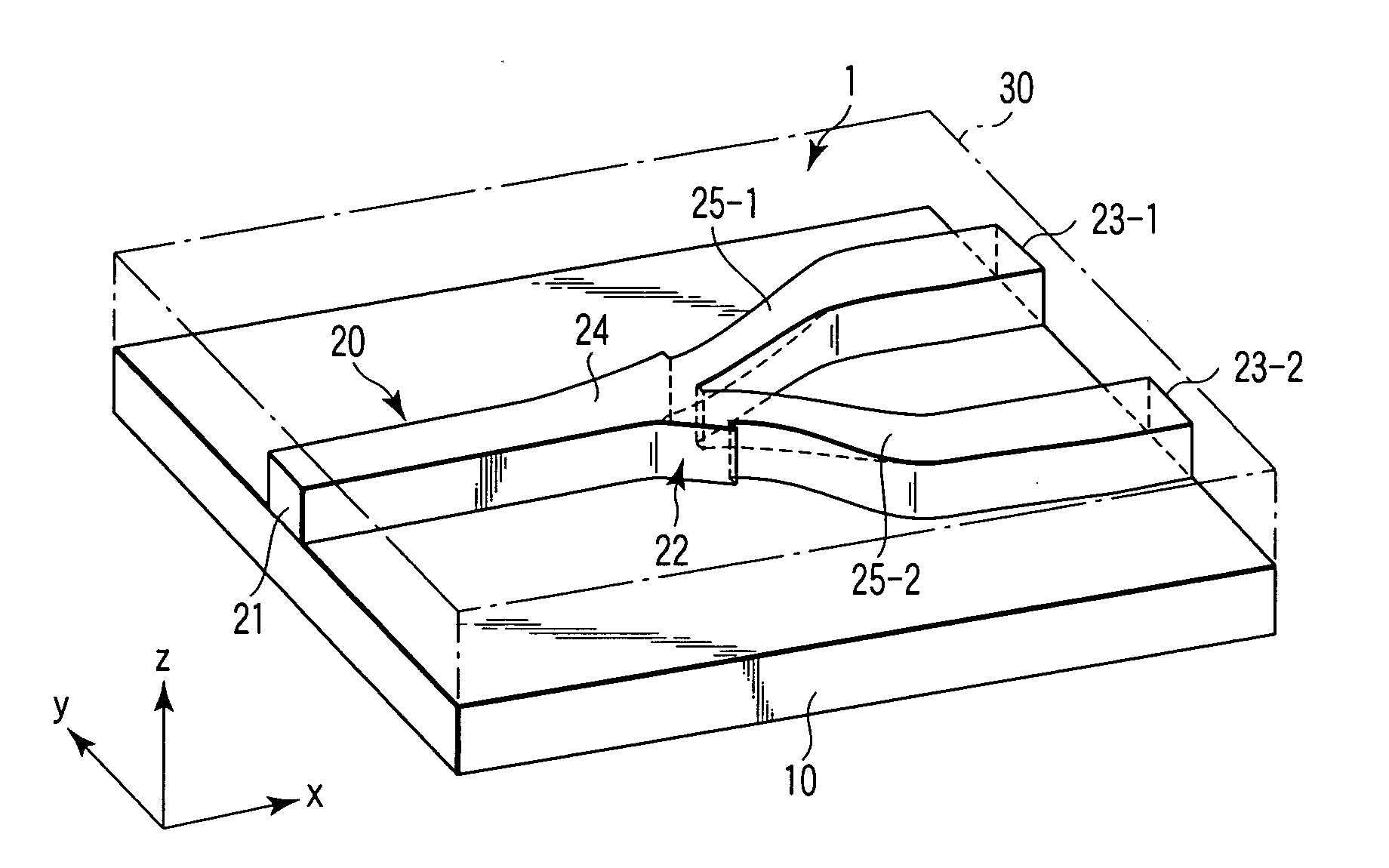
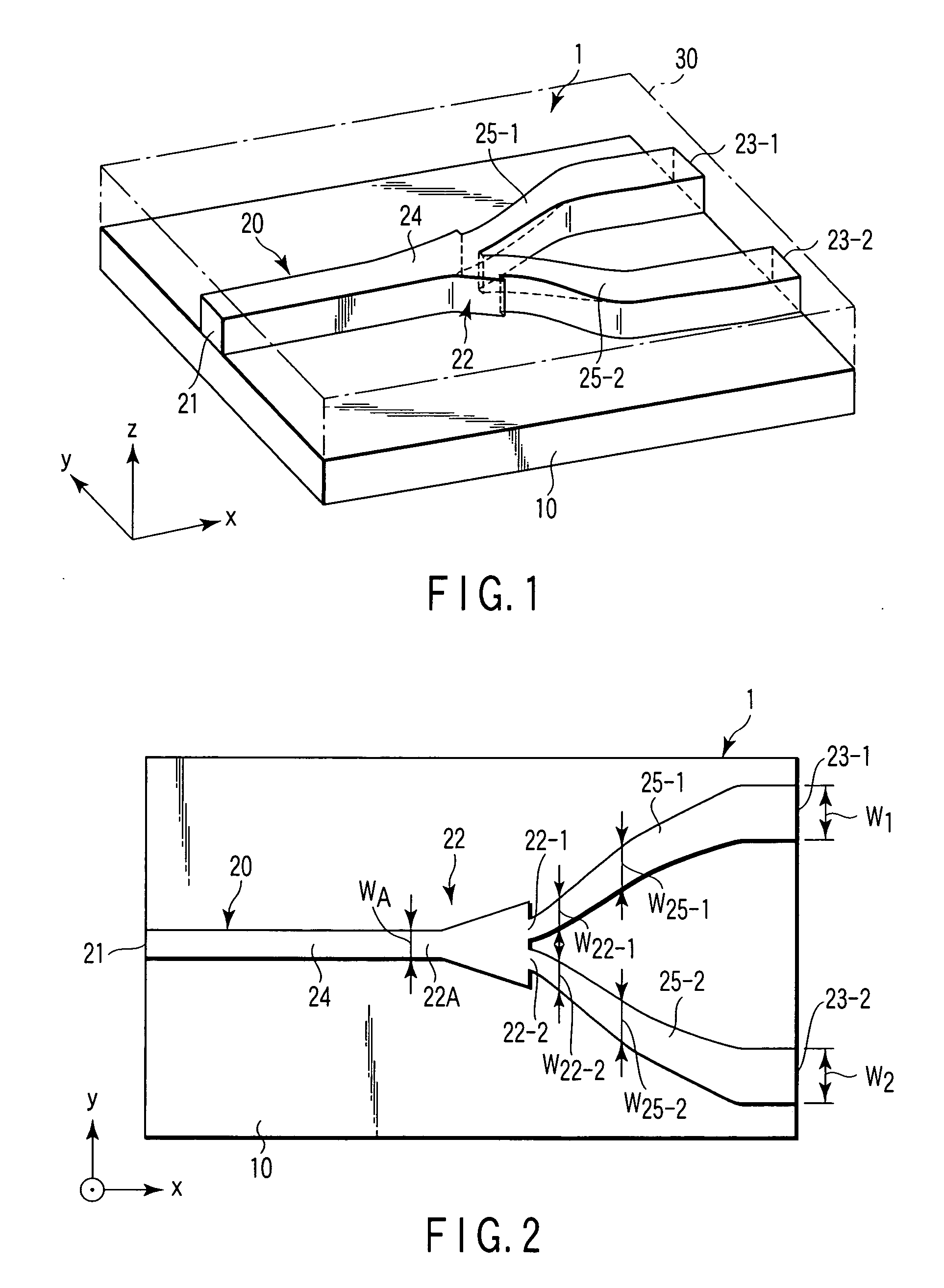
[0039]FIG. 1 is a schematic illustration explaining an example of an optical branching unit according to an embodiment of the invention.

[0040]As shown in FIG. 1, an optical branching unit 1 has a substrate composed mainly of silicon dioxide (SiO2), and an optical waveguide structure 20 formed by patterning in a predetermined shape on the substrate 10. The space surrounding the optical waveguide structure 20 is covered by a member functioning as a clad layer 30 to make the optical waveguide structure 20 usable as a core. A relative index difference between the core portion (optical waveguide structure 20) and clad area (clad layer 30) is 0.45%.

[0041]The optical waveguide structure 20 includes an input end 21 to input a light beam (an optical signal) supplied through a not-show optical transmission member, such as an optical fiber and an optical branching unit in a pr...


PUM


Abstract

In an optical branching unit according to the invention, the cross section shape in an area of a front stage to branch to two output waveguides in the optical branch is a rectangle or a non-circle with different vertical-to-horizontal ratio, including an area that the length along the surface of the substrate is defined to be shorter than the length in the direction orthogonal to the surface of a substrate, the cross section at the output ends of the output waveguide is a rectangle or a non-circle with a different vertical-to-horizontal ratio, where the length along the surface of the substrate is defined to be longer than the length in the direction orthogonal to the surface of the substrate.

Description

CROSS-REFERENCE TO RELATED APPLICATIONS[0001]This is a Continuation Application of PCT Application No. PCT / JP2005 / 008704, filed May 12, 2005, which was published under PCT Article 21(2) in Japanese.[0002]This application is based upon and claims the benefit of priority from prior Japanese Patent Application No. 2004-145032, filed May 14, 2004, the entire contents of which are incorporated herein by reference.BACKGROUND OF THE INVENTION[0003]1. Field of the Invention[0004]The present invention relates to an optical branching unit, which is usable in the field of optical communication, and outputs a light beam input to an input end to a plurality of output end.[0005]2. Description of the Related Art[0006]In an optical branching unit using an optical waveguide, it is particularly desired as an optical characteristic that the wavelength uniformity of insertion loss is not varied in each branching destination, namely, the wavelength uniformity of each destination is substantially equal.[...

Claims


Application Information

Patent Timeline
Patent Type & Authority Patents(United States)
IPC IPC(8): G02B6/42G02B6/10G02B6/12G02B6/122G02B6/125G02B6/30
CPCG02B6/1228G02B6/125G02B2006/1215
Inventor TAKAHASHI, FUMIOISHIKAWA, KOJITAJIMA, NORIHIRO
Owner ORMON CORP
Why Eureka
Try Eureka