
Die casting process incorporating computerized pattern recognition techniques

a pattern recognition and computerized technology, applied in the field of die casting processes, can solve the problems of aluminum alloy die castings produced at the first facility often proving unsuitable for their intended later use, and the operation of multiple dies is usually slower

Inactive Publication Date: 2008-04-29
PACE IND LLC A DELAWARE CO
View PDF5 Cites 9 Cited by
  • Summary
  • Abstract
  • Description
  • Claims
  • Application Information

AI Technical Summary

Benefits of technology

"The present invention is a method for manufacturing castings by selecting conditions and manufacturing castings under those conditions. The castings are then analyzed for defects and the information obtained from the analysis is used to improve future castings. The method includes selecting a set of conditions, manufacturing castings under those conditions, analyzing the castings for defects, and creating a database of defects and physical parameter measurements. This database is used to identify and avoid defective castings during manufacturing. The method also includes marking each casting with a unique identifier and performing tests on the castings to gather additional defect information. The invention is particularly useful for manufacturing chrome-plated, metal-alloy castings."

Problems solved by technology

Multiple dies are usually slower to operate than single dies but will give higher production rates for the same labor costs.
A drawback to this process has been that, once subjected to the chrome-plating process, the aluminum alloy die castings produced at the first facility often proved unsuitable for their intended later use.
For example, using conventional die casting techniques, chrome-plated aluminum alloy die castings to be used as either a rocker cover or rocker housing for the aforementioned FL Series motorcycles were experiencing a rejection rate of about 40% due to defects noted during inspections of the die castings conducted during and / or after the chrome-plating process.
While the rejection rate has been attributed to a variety of causes, one such cause is that a number of the various types of defects which commonly occur during the manufacture of an aluminum alloy die casting can remain unnoticed until after an attempt has been made to chrome-plate the die casting.

Method used


Image

  • Die casting process incorporating computerized pattern recognition techniques
  • Die casting process incorporating computerized pattern recognition techniques
  • Die casting process incorporating computerized pattern recognition techniques

Examples


Embodiment Construction

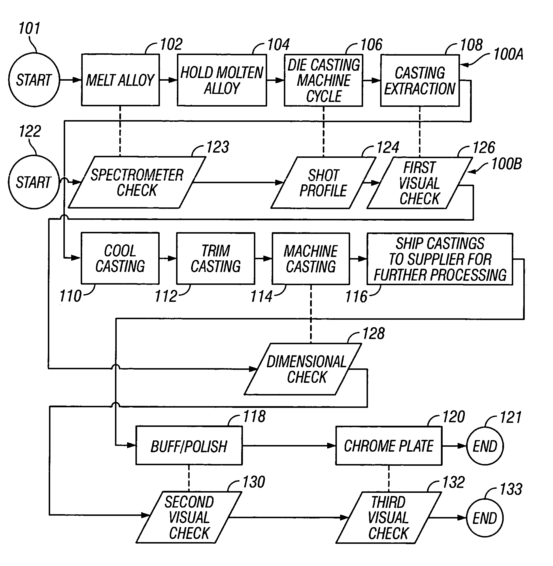
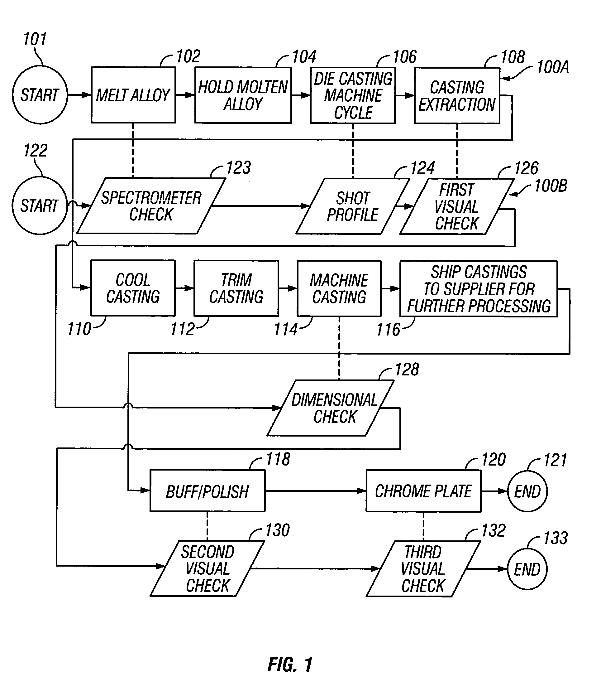
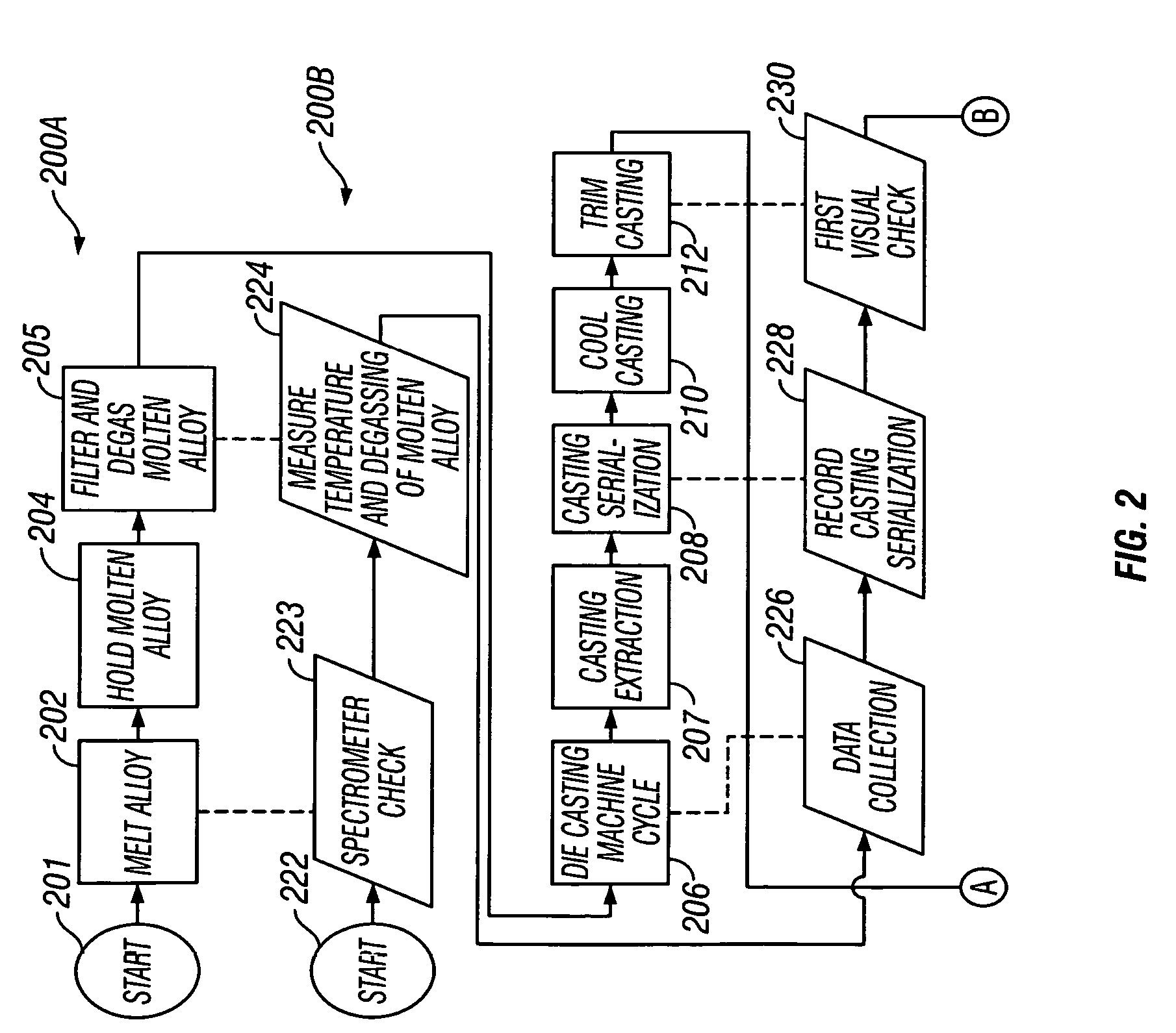
[0023]FIG. 1 shows a conventional die casting process 100a suitable for use in the manufacture of die castings, for example, chrome-plated aluminum alloy rocker cover and rocker housing die castings. The die casting process 100a commences at step 101 and, proceeding on to step 102, a primary furnace or similar heating device is used to melt a metal or metal alloy, for example, an aluminum alloy, by heating an amount of the solid metal or metal alloy to an elevated temperature above its melting point. For example, if an aluminum alloy was to be melted using the primary furnace, a temperature of about 1,300 degrees Fahrenheit would be suitable. Once melted, the molten metal or metal alloy is transported, for example, using a bull ladle, to a secondary furnace or similar heating device where the molten metal or metal alloy is held, at step 104, in advance of initiation of a die cast machine cycle, at step 106, by a die cast machine. Proceeding on to step 106, a die cast machine cycle i...


PUM

PropertyMeasurementUnit
temperatureaaaaaaaaaa

Abstract

A die casting process using pattern recognition techniques to identify those die castings manufactured under conditions likely to produce a die casting which would subsequently prove unacceptable for use. By promptly identifying such die castings, they may be discarded before being shipped to a remote facility for further processing. As a result, the rejection rate of die castings at the remote facility may be reduced and the raw materials used to form the discarded die castings may be more readily recycled.

Description

CROSS-REFERENCE TO RELATED APPLICATIONS[0001]This application is a Continuation of Ser. No. 10 / 208,416 now U.S. Pat. No. 6,776,212 entitled “Die Casting Process Incorporating Computerized Pattern Recognition Techniques,” filed Jul. 30, 2002, which, in turn, was related to U.S. Provisional Patent Application Ser. No. 60 / 390,779, filed Jun. 21, 2002, both of which are assigned to the Assignee of the present application and hereby incorporated by reference as if reproduced in their entirety.[0002]This application is also related to U.S. Pat. No. 6,779,583 entitled “Die Casting Process Iterative Process Parameter Adjustments” and U.S. Pat. No. 6,772,821 entitled “System for Manufacturing Die Castings,” both of which were filed on Jul. 30, 2002 and are assigned to the Assignee of the present application and are hereby incorporated by reference as if reproduced in their entirety.STATEMENT REGARDING FEDERALLY SPONSORED RESEARCH OR DEVELOPMENT[0003]Not applicable.REFERENCE TO A MICROFICHE A...

Claims


Application Information

Patent Timeline
Patent Type & Authority Patents(United States)
IPC IPC(8): B22D46/00B22D17/32
CPCB22D17/32B22D46/00
Inventor FULTON, ARNIEZHU, YANBOMAR, MICHAEL
Owner PACE IND LLC A DELAWARE CO
Learn More