Inkjet recording apparatus and recording medium movement control method
a recording medium and movement control technology, applied in the direction of thin material processing, printing, article separation, etc., can solve the problems of large error, output fluctuation under influence, and inconvenient movement of recording medium surface, and achieve high-precision movement of recording medium and enhanced reliability in mark detection
- Summary
- Abstract
- Description
- Claims
- Application Information
AI Technical Summary
Benefits of technology
Problems solved by technology
Method used
Image
Examples
embodiment-1
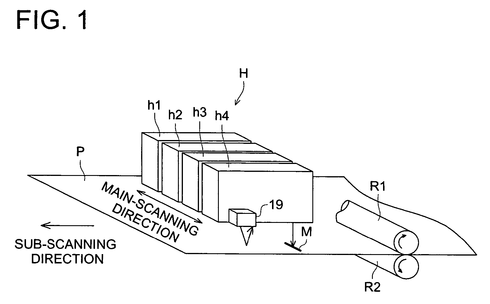
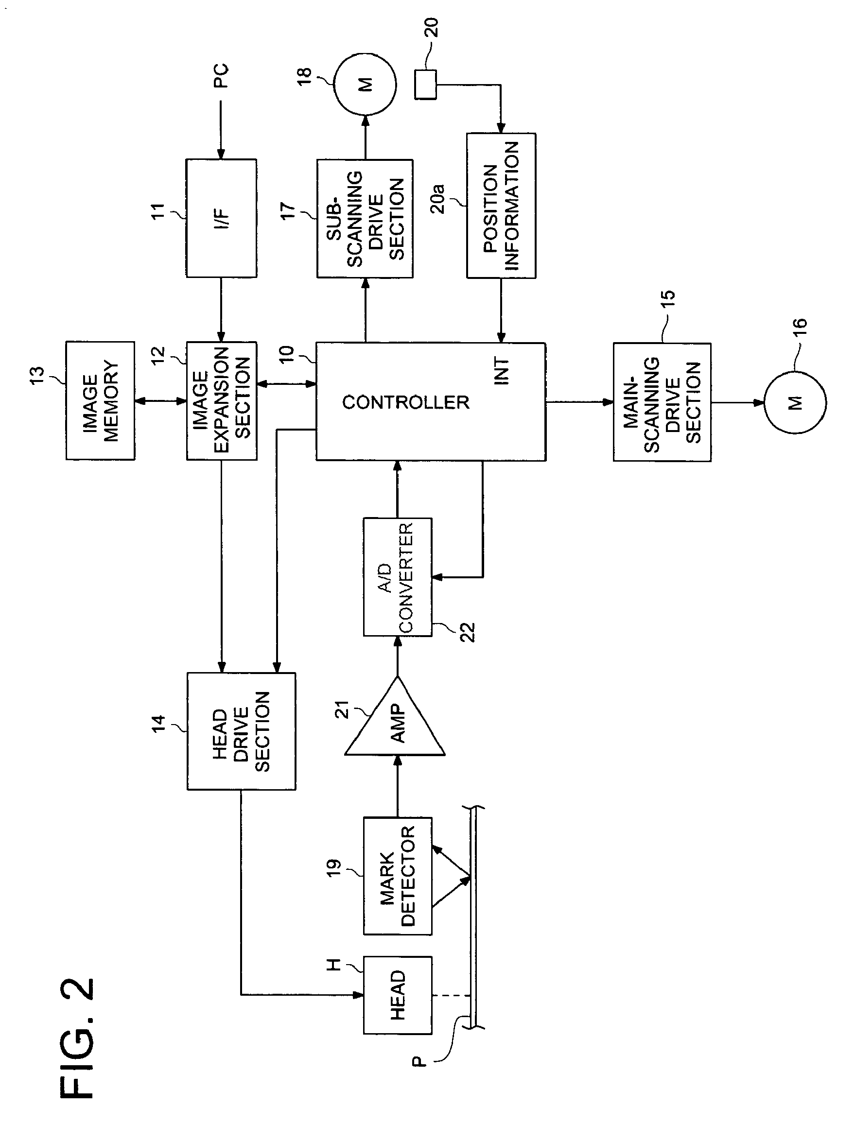
[0095]FIG. 1 is a configuration diagram representing the overview of an inkjet recording apparatus of the present invention, and FIG. 2 is a block diagram representing the same. In the diagram, H denotes a recording head. The figures show four heads h1 through h4 corresponding to four colors—Y, M, C and K, respectively, as example. The number of heads constituting the recording head H is not restricted in particular.
[0096]On the bottoms of heads h1 through h4, many nozzles (not illustrated) are arranged in a line in the direction orthogonal to the main scanning direction of the recording head H. Ink in the form of minute ink particles is discharged from the nozzles of heads h1 through h4 downward in a predetermined timing, as shown in FIG. 1, whereby a desired image based on image data is recorded on the recording medium P.
[0097]The image data is stored once into the image memory 13 through the I / F section 11 and image expansion section 12 from the external PC (personal computer), a...
embodiment-2
[0156]The following describes the second embodiment. The same processes and apparatuses as those of the aforementioned first embodiment will not be described to avoid duplication.
[0157]The arrangement before the mark M on the recording medium is detected by the mark detector 19 is the same as that of the embodiment 1.
[0158]The output signal issued when the mark M on the recording medium has been detected by the mark detector 19 is amplified to a predetermined signal level by the AMP 21 shown in FIG. 12. Then it is sent to a clamping section 122.
[0159]The present embodiment is provided with a rotary encoder (not illustrated) constituting the position information detecting section for the recording medium P. As shown in FIG. 12, the number of pulses of the rotary encoder outputted synchronously with the movement of the recording medium P by a pair of rollers R1 and R2 driven by the sub-scanning motor 18 is detected by the encoder sensor 20. The number of pulses detected by the encoder...
embodiment-3
[0189]As shown in FIG. 17, a mark detector 160 as mark detecting means is provided on either one end of the recording head H in the main scanning direction. As shown in FIG. 18, this mark detector 160 consists of a reflection type optical sensor comprising:
[0190]a light emitting device 163 for emitting detection light for applying detection light obliquely to the surface of the recording medium P through the opening 162;
[0191]a condensing lens 164 for condensing and converging the detection light on the surface of the recording medium P;
[0192]a condensing lens 165 for condensing the reflected light formed by reflection of the detection light from the surface of the recording medium P; and
[0193]a light receiving device 166 for receiving the detection light condensed by the condensing lens 165; they are contained in the casing 161. The mark M is detected by detecting the change in the amount of light when the detection light irradiated on the recording medium P has passed through the ...
PUM
 Abstract
Description
Claims
Application Information
 - R&D
- Intellectual Property
- Life Sciences
- Materials
- Tech Scout
- Unparalleled Data Quality
- Higher Quality Content
- 60% Fewer Hallucinations
Browse by: Latest US Patents, China's latest patents, Technical Efficacy Thesaurus, Application Domain, Technology Topic, Popular Technical Reports.
© 2025 PatSnap. All rights reserved.Legal|Privacy policy|Modern Slavery Act Transparency Statement|Sitemap|About US| Contact US: help@patsnap.com


