
Low magnetic leakage high voltage transformer

a high-voltage transformer, low-magnet leakage technology, applied in the direction of transformer/inductance details, inductance, electrical equipment, etc., can solve the problems of high manufacturing cost of tft lcd, inability to reduce the size of tft lcd to meet the market trend of light, thin, short and small, and save manufacturing cost and size of tft lcd. , to achieve the effect of preventing short circuit and

Inactive Publication Date: 2008-04-29
TAIPEI MULTIPOWER ELECTRONICS
View PDF4 Cites 18 Cited by
  • Summary
  • Abstract
  • Description
  • Claims
  • Application Information

AI Technical Summary

Benefits of technology

"The present invention is a low magnetic leakage high voltage transformer that has several technical effects. Firstly, it stabilizes the electric current of lamp tubes connected to it, extending their work life. Secondly, it prevents magnetic saturation and overheat, increasing the electric power capacity of the transformer. Thirdly, it prevents short circuit by increasing the creepage distance between the different parts of the transformer. Finally, it allows for the output of two high voltages for driving a load or loads."

Problems solved by technology

However, because each CCFL uses a respective circuit (electronic ballast), the manufacturing cost of the TFT LCD is high, and the size of the TFT LCD cannot be reduced to meet the market trend toward light, thin, short and small.
The use of such a transformer in a TFT LCD greatly saves the manufacturing cost and size of the TFT LCD.
However, this design cannot eliminate magnetic interference between windings, and the secondary windings may output different amount of electric energy to the connected lamps, resulting in insufficient brightness of the lamps or damage to the lamps.
However, because the windings use one common magnetic PATH, magnetic interference will occur between each two adjacent windings, resulting in unstable power output and uneven brightness of the connected lamp tubes.
Further, the use of one common magnetic PATH by multiple primary windings and secondary windings will cause magnetic saturation, resulting in loss of magnetization and overheat of the FERRITE core set, and the power capacity of the high voltage transformer will drop.
Further, the arrangement of the multiple primary windings and secondary windings greatly increases the magnetic path length, resulting in a low leakage inductance and causing it unable to achieve the desired resonant frequency.

Method used


Image

  • Low magnetic leakage high voltage transformer
  • Low magnetic leakage high voltage transformer
  • Low magnetic leakage high voltage transformer

Examples


Embodiment Construction

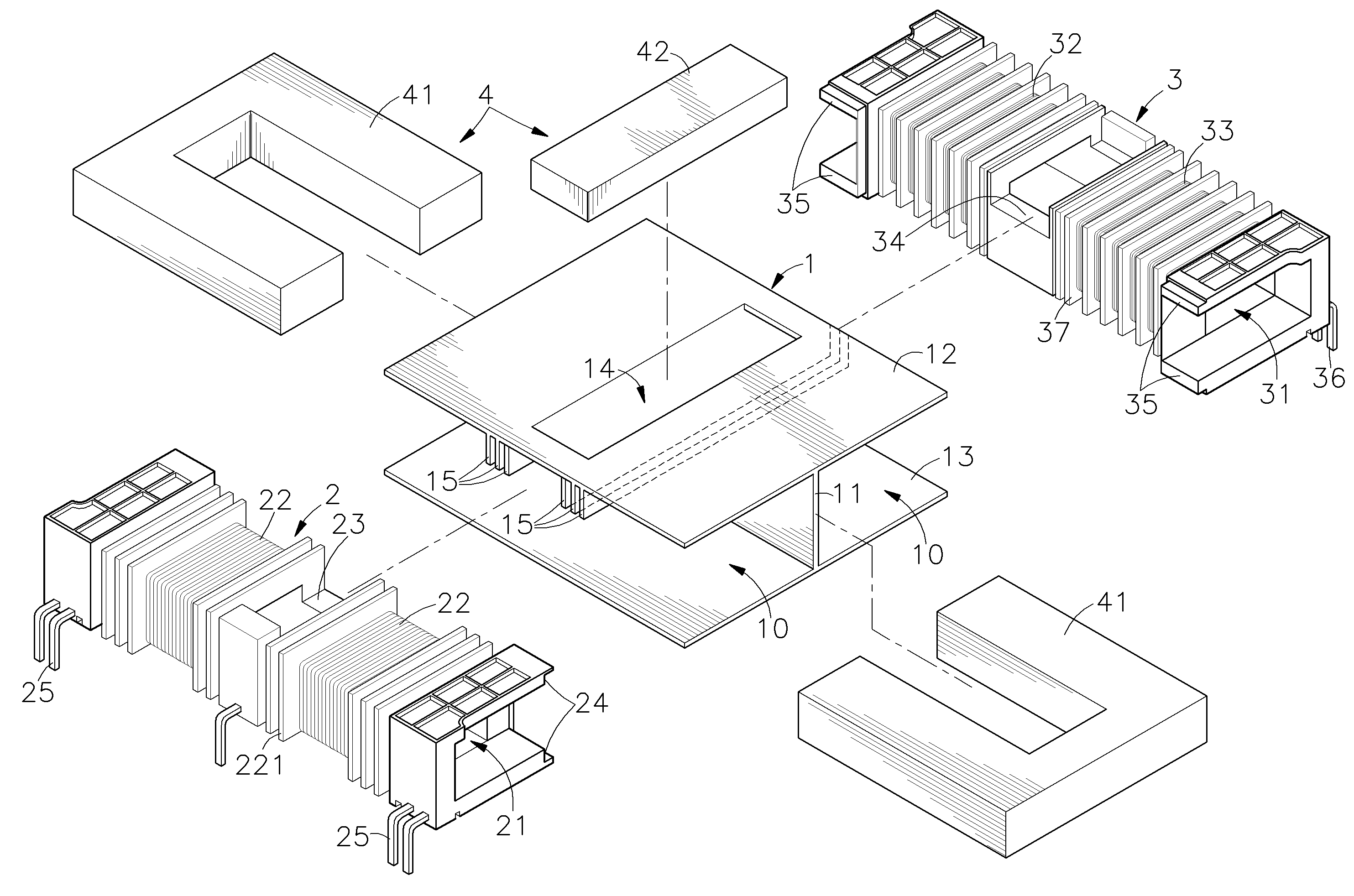
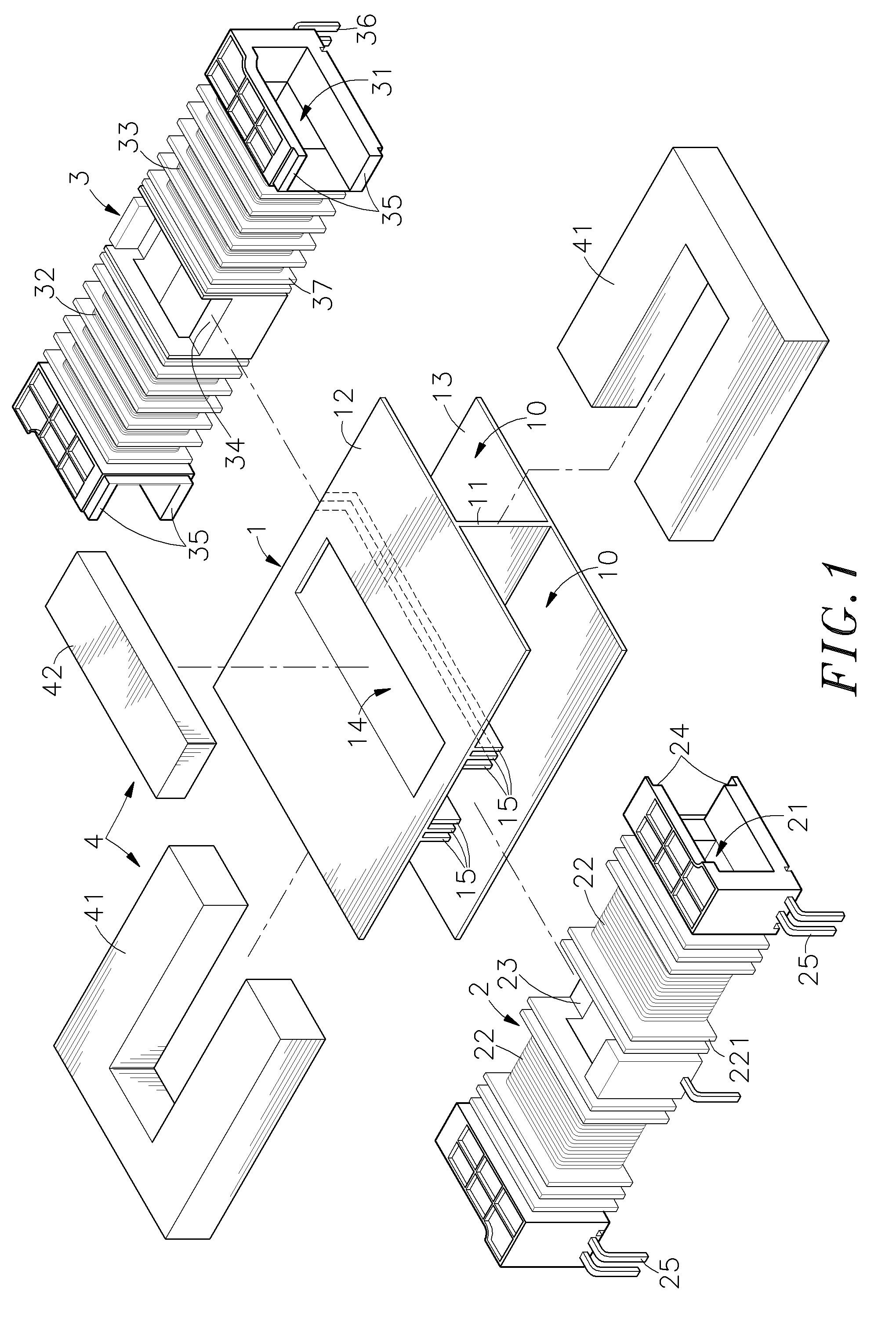
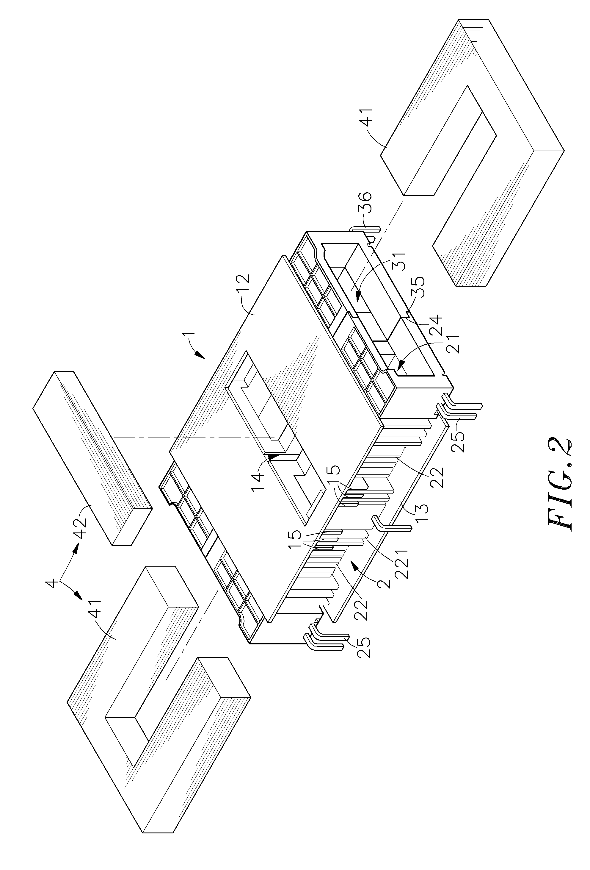
[0023]Referring to FIGS. 1˜3, a low magnetic leakage high voltage transformer in accordance with the first embodiment of the present invention is shown comprised of an electrically insulative holder frame 1, a primary winding bracket 2, a secondary winding bracket 3 and an FERRITE core set 4.

[0024]The cross section of the electrically insulative holder frame 1 shows an I-shaped profile. Further, the electrically insulative holder frame 1 comprises a vertical middle wall 11, a horizontal top wall 12 at the top side of the vertical middle wall 11, and a horizontal bottom wall 13 at the bottom side of the vertical middle wall 11. The two horizontal top and bottom walls 12 and 13 define two receiving spaces 10 at two sides of the vertical middle wall 11. Further, the horizontal top wall 12 has an insertion slot 14 on the middle, and a plurality of baffle flanges 15 downwardly extending from the bottom surface and arranged in parallel at two sides of the insertion slot 14.

[0025]The prima...


PUM

PropertyMeasurementUnit
voltageaaaaaaaaaa
voltageaaaaaaaaaa
magnetic fieldaaaaaaaaaa

Abstract

Disclosed is a low magnetic leakage high voltage transformer in which two winding brackets are mounted in an electrically insulative holder frame to hold two primary windings and two secondary windings at two sides, two U-shaped FERRITE cores are inserted into the winding brackets from two sides and abutted against each other, and a straight FERRITE core is inserted into an insertion slot on the electrically insulative holder frame into contact with the abutted U-shaped FERRITE cores and isolated from the primary windings and the secondary windings by baffle flanges of the electrically insulative holder frame, and two electrically insulative caps are capped on the winding brackets and abutted against two opposite sides of the electrically insulative holder frame to increase the creepage distance between conducting terminals of the windings and the FERRITE cores, for enabling the secondary windings to output two high voltages stably for driving multiple loads.

Description

BACKGROUND OF THE INVENTION[0001]1. Field of the Invention[0002]The present invention relates to transformers and more particularly, to a low magnetic leakage high voltage transformer, which provides two output voltages to drive multiple loads.[0003]2. Description of the Related Art[0004]German scientist Karl Ferdinand Braun developed the first controllable CRT in 1897. However, it wasn't until the late 1940s that CRTs were used in the first television sets. Nowadays, various new display devices including TFT LCDs, PDPs, FPDs, etc. have been developed and have appeared on the market. It is predicated that TFT LCDs will soon completely take the place of CRTs on market. Currently, the backlight of a TFT LCD uses a number of CCFLs (Cold Cathode Fluorescent Lamps). In order to drive these CCFLs, each CCFL uses one respective circuit (electronic ballast). Because a CCFL discharges electricity, it produces negative resistance. When multiple CCFLs are connected in parallel to a transformer...

Claims


Application Information

Patent Timeline
Patent Type & Authority Patents(United States)
IPC IPC(8): H01F27/24
CPCH01F3/12H01F27/306H01F27/326H01F30/04H01F38/10H01F27/325
Inventor YANG, CHING-SHENGWU, SU-HUACHENG, YUAN-KUEI
Owner TAIPEI MULTIPOWER ELECTRONICS
Learn More