
Single-to-multi mode converter and optical code division multiple access system using the same

a converter and multi-mode technology, applied in the field of single-to-multi-mode converters, can solve the problems of difficult cutting and connecting processes, difficult to accurately align the axes of optical fibers with each other according to a designed value, and inconvenient uniform field distribution of a fundamental mode of single-mode optical fibers, etc., to achieve the effect of reducing excess noise and maximizing the number of multiple modes converted

Active Publication Date: 2008-04-29
ELECTRONICS & TELECOMM RES INST
View PDF13 Cites 12 Cited by
  • Summary
  • Abstract
  • Description
  • Claims
  • Application Information

AI Technical Summary

Benefits of technology

[0016]An object of the present invention is to provide a mode converter capable of uniformly coupling the power of a fundamental mode of a single mode optical waveguide to each mode of a multi-mode optical waveguide.
[0017]Another object of the present invention is to maximize the number of multiple modes converted from a single mode.
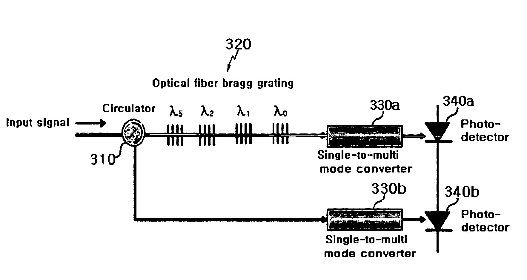
[0018]Yet another object of the present invention is to considerably reduce the excess noise in an optical communication network and in optical signal processing using an incoherent light source by using a very simple method.

Problems solved by technology

With this mode converter, however, it is very difficult to accurately align the axes of optical fibers with each other according to a designed value to connect the optical fibers to each other.
Furthermore, a field distribution of a fundamental mode of the single-mode optical fiber is not suitable for uniformly coupling the power of a fundamental mode of the single-mode optical fiber to each mode of the multi-mode optical fiber during the mode conversion process.
However, the cutting and connecting processes are difficult to carry out.
Moreover, it is not easy to decrease errors in the processes.
Thus, it is difficult to uniformly couple the power of the fundamental mode of single mode fiber to each mode of multi-mode fiber.
In an optical communication network or an optical access network, excess noise or speckle noise caused by a beat reduces a signal-to-noise ratio to decrease transmission quality and restrict the number of subscribers.
In particular, in the case of an optical access network using code division multiple access, the excess noise is an essential factor that restricts the number of subscribers because the excess noise is in proportion to the square of the number of subscribers.
Noises generated in optical communications include an optical intensity noise that is generated in a laser diode of a transmitter, and a shot noise and a thermal noise generated in a receiver.
This generates the excess noise.
Particularly, in a spectrally encoded optical CDMA network using a broadband incoherent light source such as a superluminescent light emitting diode as a light source, a large excess noise is generated which restricts the number of subscribers.
Furthermore, the performance of an optical fiber gyroscope using the broadband incoherent light source is restricted by the excess noise.
However, an optical loss in the splitter and recombiner is very large during the splitting and recombining process, respectively.
Moreover, the method of simply connecting a single-mode optical fiber to a multi-mode optical fiber has very low mode conversion efficiency.

Method used


Image

  • Single-to-multi mode converter and optical code division multiple access system using the same
  • Single-to-multi mode converter and optical code division multiple access system using the same
  • Single-to-multi mode converter and optical code division multiple access system using the same

Examples


Embodiment Construction

[0037]In the following detailed description, only the preferred embodiment of the invention has been shown and described, simply by way of illustration of the best mode contemplated by the inventor(s) of carrying out the invention. As will be realized, the invention is capable of modification in various obvious respects, all without departing from the invention. Accordingly, the drawings and description are to be regarded as illustrative in nature, and not restrictive.

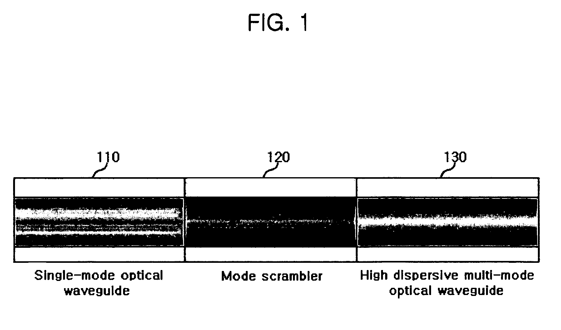
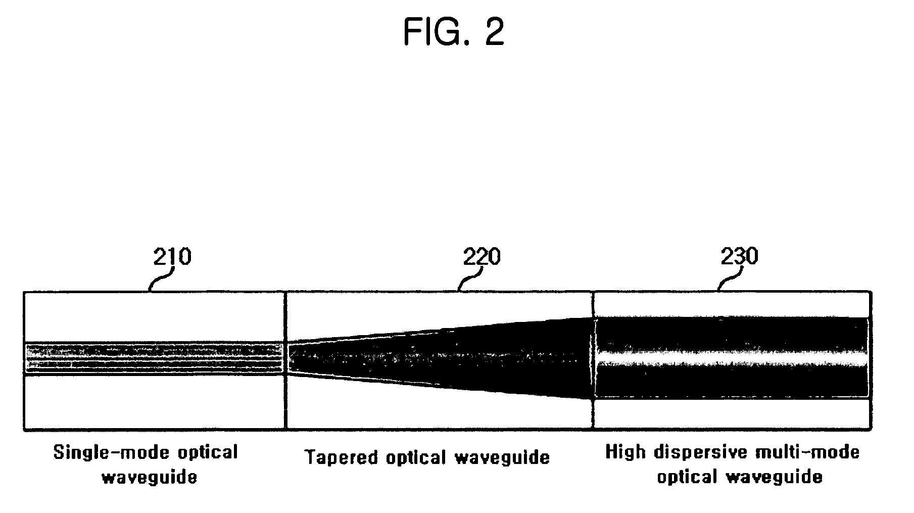
[0038]FIG. 1 illustrates a mode converter according to a first embodiment of the present invention. Referring to FIG. 1, the mode converter according to the first embodiment of the present invention includes a single-mode optical waveguide 110, a mode scrambler 120, and a multi-mode optical waveguide 130.

[0039]The single-mode optical waveguide 110 is formed of a single-mode optical fiber, and the multi-mode optical waveguide 130 is formed of a high dispersion multi-mode optical fiber. Accordingly, the mode converter ca...


PUM


Abstract

A single-to-multi mode converter and an optical code division multiple access system using the same. The mode converter includes first, second, and third optical waveguides. The first optical waveguide is formed of a single-mode optical fiber and outputs a single-mode optical signal. The second optical waveguide converts the single-mode optical signal output from the first optical waveguide to a multi-mode optical signal and allows the optical power of the single-mode optical signal to be coupled to each mode of the multi-mode optical signal. The third optical waveguide is formed of a multi-mode optical fiber and transmits the multi-mode optical signal output from the second optical waveguide.

Description

CROSS REFERENCE TO RELATED APPLICATION[0001]This application claims priority to and the benefit of Korea Patent Application No. 2003-96295 filed on Dec. 24, 2003 in the Korean Intellectual Property Office, the content of which is incorporated herein by reference.BACKGROUND OF THE INVENTION[0002](a) Field of the Invention[0003]The present invention relates to a mode converter, and more particularly, to a single-to-multi mode converter that converts a single mode to a multi-mode and a code division multiple access system using the same.[0004](b) Description of the Related Art[0005]A mode converter is a device that converts modes used in optical communication networks. U.S. Pat. No. 5,077,815 discloses a mode converter, which directly connects a single-mode optical fiber to a multi-mode optical fiber. The mode converter converts a single-mode to a multi-mode through core axial displacement between the single-mode optical fiber and the multi-mode optical fiber. With this mode converter,...

Claims


Application Information

Patent Timeline
Patent Type & Authority Patents(United States)
IPC IPC(8): H04B10/08H04B10/12G02B6/14H04B10/02G02B6/34H04B10/2581
CPCG02B6/14H04B10/2581G02B6/2932H04B10/00
Inventor CHO, SUNG-CHANKIM, BONG-KYUYEON, YOUNG-HEEKIM, BYOUNG-WHI
Owner ELECTRONICS & TELECOMM RES INST
Learn More