Low-latency synchronous-mode sync buffer circuitry having programmable margin

Inactive Publication Date: 2008-04-29
ADVANCED MICRO DEVICES INC
View PDF5 Cites 4 Cited by
  • Summary
  • Abstract
  • Description
  • Claims
  • Application Information

AI Technical Summary

Benefits of technology

[0008]There is a need for an arrangement in a communications system that provides a precise synchron

Problems solved by technology

However, it is also often the case that it is not desired to change the clock frequency at which the remainder of the local chip runs (i.e., the local clock domain), perhaps because it connects to another bus of a specific defined frequency, or has been tuned to run most efficiently at a particular frequency.
However, the PLL circuits will induce jitter (both correlated and uncorrelated between the PLLs) across the target clocks, causing the clocks to move relative to their ideal alignment to th

Method used


Image

  • Low-latency synchronous-mode sync buffer circuitry having programmable margin
  • Low-latency synchronous-mode sync buffer circuitry having programmable margin
  • Low-latency synchronous-mode sync buffer circuitry having programmable margin

Examples


Embodiment Construction

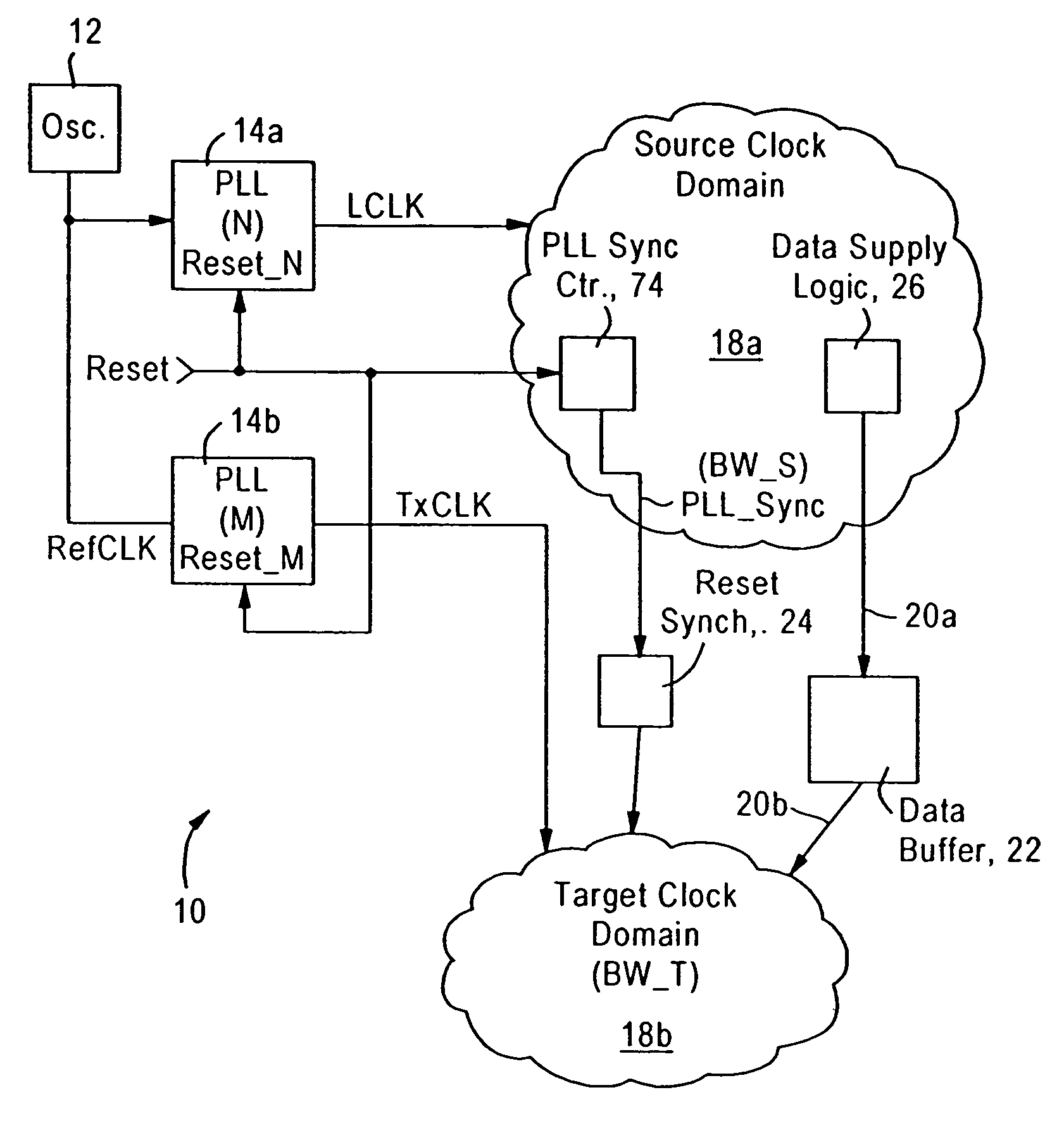
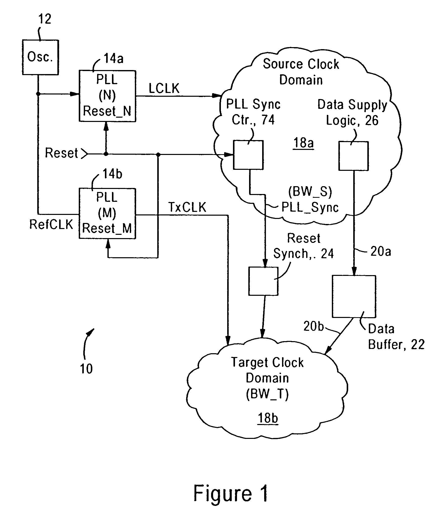
[0021]The disclosed embodiment is directed to an integrated circuit, for example a microprocessor or a device that interfaces with the microprocessor via a high-speed link such as a HyperTransport™ link, having a transmit buffer circuit configured for outputting synchronous data signals based on synchronization between a local clock generated according to a local clock domain, and a transmit clock identifying a transmit clock domain, the local clock and the transmit clock generated based on the same reference frequency. As described below, however, the local clock and the transmit clock can have a relationship of an integer ratio of frequencies, with some jitter.

[0022]FIG. 1 is a diagram illustrating a synchronous transmission system 10 including an oscillator12 configured for generating a reference clock signal (RefCLK), phase locked loops (PLLs) 14a, 14b configured for generating a local clock (LCLK) (i.e., a source clock) and a transmit clock (TxCLK) (i.e., a target clock) at res...


PUM


Abstract

Synchronization is attained between a source clock domain and a target clock domain of arbitrary frequency ratios and each of which periodically has edges nominally aligned to edges of a reference clock signal, marked by the assertion of a periodic sync signal. The periodic sync signal, synchronous with the source clock, is used to output to an unload pointer counter in the target clock domain the deassertion of a reset signal prior to the nominal alignment of the source clock and the target clock for sampling on the nominally aligned target clock edge. The deassertion of the reset signal is output to a load pointer in the source clock domain coincident with the nominally-aligned edges of the source clock and the target clock. Both loading and unloading start based on the reset deassertion being sampled on the nominally aligned edges in the appropriate clock domain.

Description

BACKGROUND OF THE INVENTION[0001]1. Field of the Invention[0002]The present invention relates to synchronization of data, and more particularly, to a low latency method of synchronizing high-speed data between two clock domains having respective clocks generated from the same timebase and having a prescribed frequency relationship.[0003]2. Background Art[0004]Newer communications systems require advanced processing of high speed digital signals in order to accommodate precise timing requirements. For example, processor-based communications systems utilize high speed bus architectures, such as HyperTransport™ bus architectures, to transfer large groups of data at high data rates. For example, the HyperTransport™ Specification specifies data transfer between discrete components (e.g., between a microprocessor and a PCI bridge) in data groups (packets) of up to 64 bytes, at prescribed data rates of 400 Megabits per second (Mbs) up to 2.0 Gigabits per second (Gbs) per wire.[0005]In some...

Claims


Application Information

Patent Timeline
IPC IPC(8): G06F1/00G06F1/12G06F3/00G06F5/00
CPCG06F5/10G06F7/68
Inventor OWEN, JONATHAN MERCER
Owner ADVANCED MICRO DEVICES INC
Why Eureka
Try Eureka