Supercharge Your Innovation With Domain-Expert AI Agents!

Component mounting apparatus

a technology for mounting apparatuses and components, applied in metal working apparatuses, manufacturing tools, transportation and packaging, etc., can solve the problems of increasing equipment costs, high mounting costs, and long operation sequences required for mounting one component, so as to increase the supporting rigidity, and reduce the number of components

Inactive Publication Date: 2008-05-06
PANASONIC CORP
View PDF14 Cites 7 Cited by
  • Summary
  • Abstract
  • Description
  • Claims
  • Application Information

AI Technical Summary

Benefits of technology

[0011]In this configuration, it is possible to enhance the operation efficiency dramatically by using a plurality of operating heads while allowing the respective operating heads to perform operations independently. Moreover, it is possible to ensure operating accuracy because the respective operating heads are mutually insensitive to vibrations and the like associated with the operations thereof. In addition, while the component mounting apparatus includes the plurality of operating heads, the Y-axis tables are arranged in parallel to the X direction along the direction of conveying the work and are laid between the supporting frames arranged in a standing manner on the both ends in the Y direction of the supporting base. Accordingly, it is possible to relatively reduce an outside dimension in the X direction of the component mounting apparatus to achieve a compact configuration. It is also possible to dramatically reduce equipment costs for a work line. Moreover, since the upper ends of the supporting frames are located lower than the height of eyes of a worker, it is possible to visually confirm operating conditions of the operating heads on the both sides from above through the interval between the Y-axis tables. Accordingly, it is possible to confirm the operating conditions easily and workability during maintenance and checkups is thereby enhanced. In addition, since the overall height dimension is set below the height of eyes of a worker, rigidity is enhanced in accordance with reduction in the height dimensions of the supporting base and the supporting frames. In this way, it is possible to enhance mounting accuracy.
[0017]Meanwhile, when the nozzle unit includes a selection mechanism for selectively transmitting the elevating operation of the elevating mechanism to a desired nozzle, it is possible to operate the desired nozzle simply by elevating the selection mechanism with the elevating mechanism. In this way, it is possible to perform operations of holding and mounting necessary components efficiently with a basic and simple configuration.

Problems solved by technology

Accordingly, an operation sequence required for mounting one component takes a long time.
In addition, the supporting frames for supporting the Y-axis tables are arranged on the both ends in the X direction and the mounting heads are configured to move inside the supporting frames in the X direction, resulting in enlargement of the component mounting apparatus in the X direction.
Therefore, the mount line becomes extremely large and thereby develops problems of increases in equipment costs and high mounting costs.
Meanwhile, a regular type of component mounting apparatus configured to arrange an X-axis robot on a Y-axis robot develops a problem that the substrate size and the number of arrangement of component supplying means are limited if a width dimension in the X direction is set constant because of a restriction of a space for disposing the Y-axis robot and a restriction of a movable range for a mounting head on the X-axis robot.
On the other hand, in order to secure the substrate size and the number of arrangement of component supplying means, the width in the X direction of the device is increased so that the device fails to achieve compact mounting equipment by reducing the width dimension of the device.
However, since such reduction in operating time has a limitation, there is a demand for a component mounting apparatus which can achieve further enhancement in mounting efficiency and reduction in equipment costs.
Therefore, the component mounting apparatus has a limitation of efficiency in the mounting operation, and also develops a problem that it is difficult to ensure mounting accuracy when the plurality of mounting heads are provided.

Method used


Image

  • Component mounting apparatus
  • Component mounting apparatus
  • Component mounting apparatus

Examples


Embodiment Construction

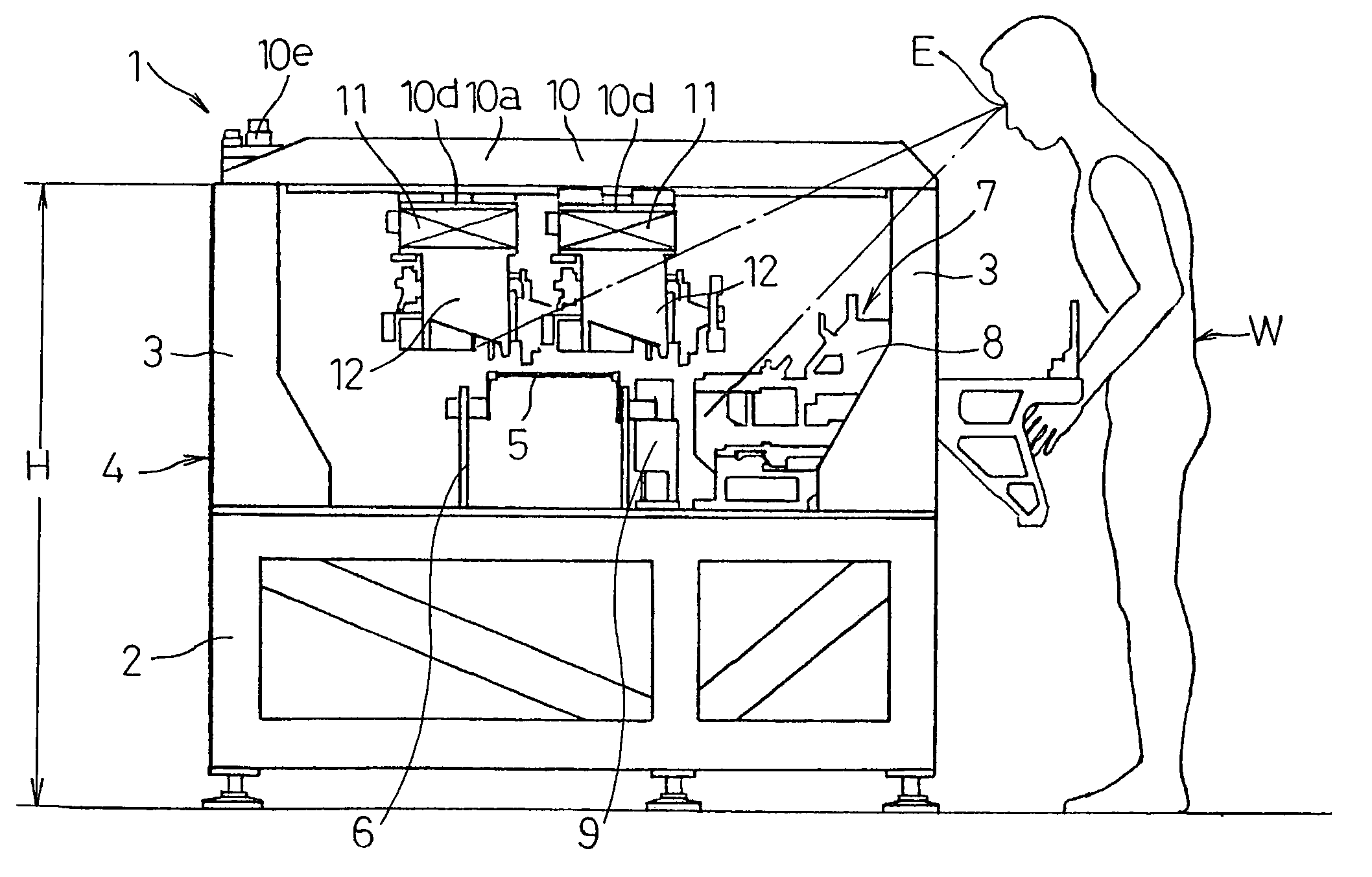
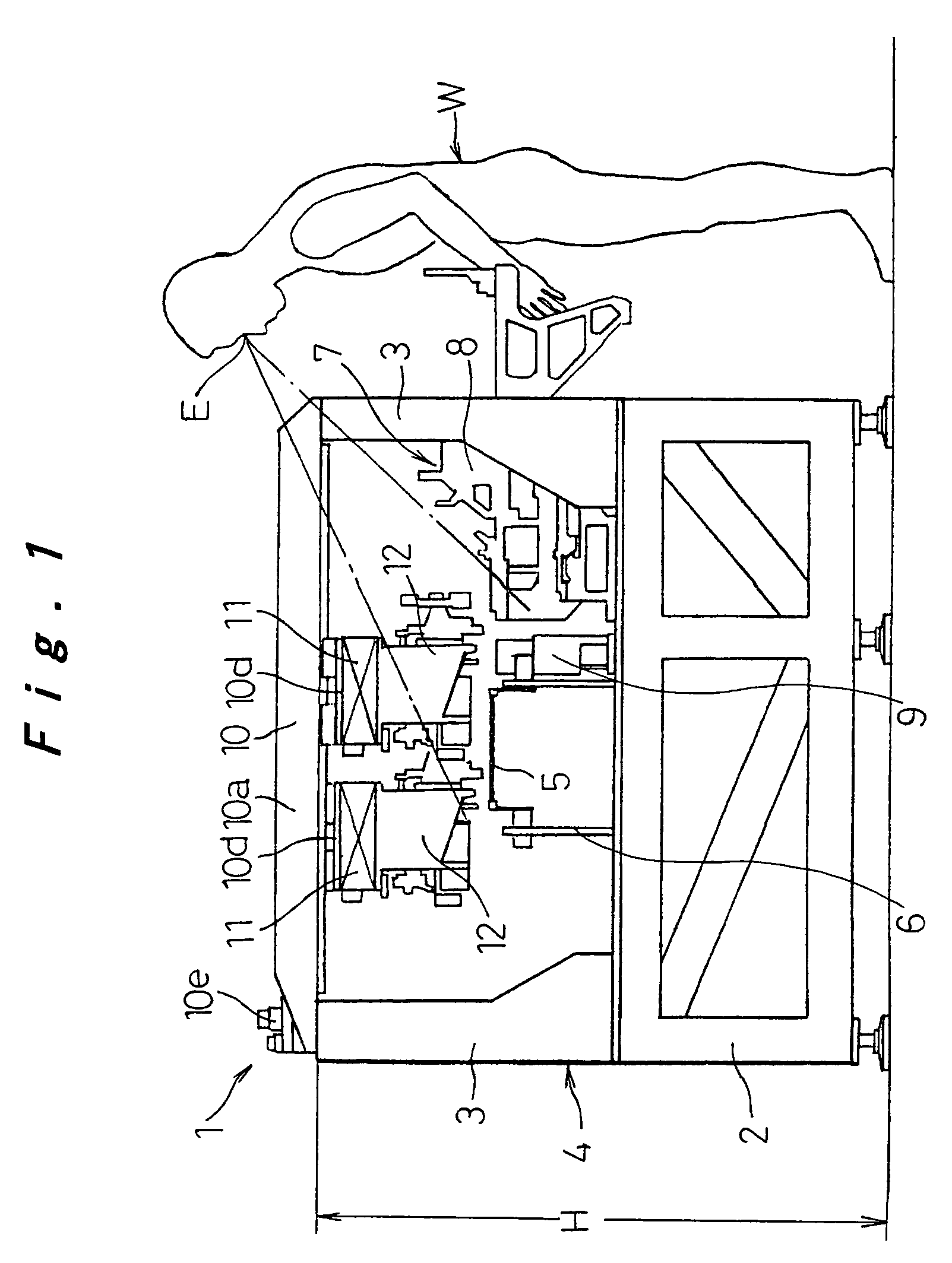
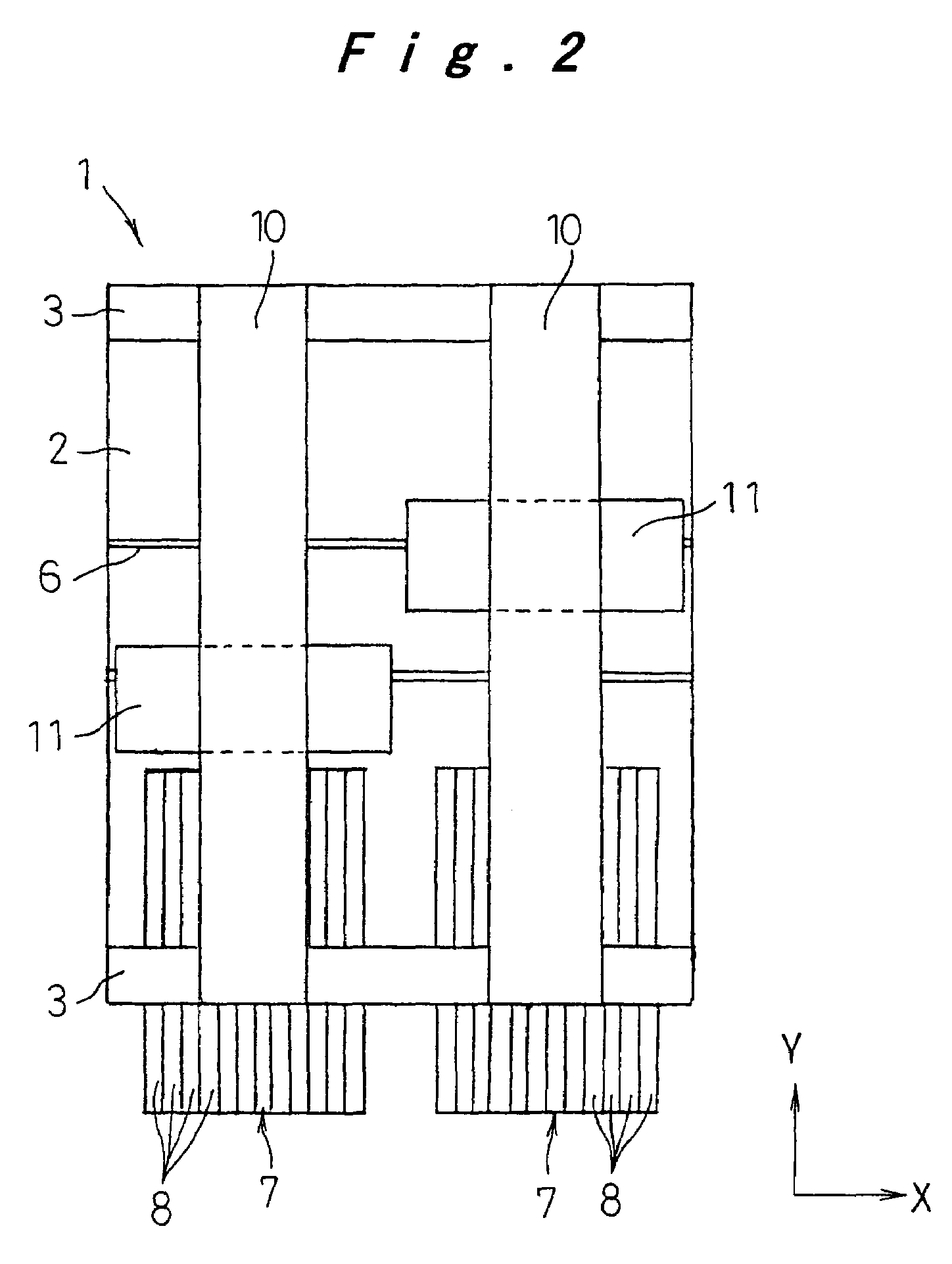
[0025]Now, an embodiment of applying a component mounting apparatus of the present invention to a component mounting apparatus for mounting electronic components on a substrate will be described with reference to FIG. 1 to FIG. 7.

[0026]In FIG. 1 to FIG. 3 showing an overall configuration of a component mounting apparatus 1 of this embodiment, gate-shaped supporting frames 3 are arranged in a standing manner on both ends in a back-to-front direction (a Y direction) on a supporting base 2, and these supporting base 2 and supporting frames 3 collectively constitute a housing 4 of the component mounting apparatus 1. The housing 4 is arranged such that a height H of upper ends of the supporting frames 3 is located below a height of eyes E of a worker W. For example, the height of eyes E is assumed to be about 1550 mm high from a floor and the height H from the floor to the upper ends of the supporting frames 3 is set in the range from 1250 to 1350 mm. In other words, if the height H is s...


PUM

PropertyMeasurementUnit
heightaaaaaaaaaa
heightaaaaaaaaaa
lengthaaaaaaaaaa

Abstract

A component mounting apparatus having a work conveyor-positioner unit is arranged on a supporting base to convey and position a substrate in an X direction. Supporting frames extend vertically from ends of the supporting base and face each other in a Y direction. The component mounting apparatus further includes a plurality of Y-axis tables extending between upper ends of the supporting frames, X-axis tables attached to movable portions of the Y-axis tables, and operating heads attached to movable portions of the X-axis tables to perform operations with respect to the substrate on the work conveyor-positioner unit. Each of the plurality of the Y-axis tables includes a movable portion at a lower part. Each of the X-axis tables includes a movable portion at a lower part and the operating heads are attached to a lower part of the movable portion of the X-axis tables.

Description

TECHNICAL FIELD[0001]The present invention relates to a component mounting apparatus configured to mount components such as electronic components on a work such as a substrate and to perform various operations with respect to the work in conjunction therewith. More specifically, the present invention relates to a component mounting apparatus configured to perform operations while moving an operating head such as a mounting head independently in an X direction and a Y direction.BACKGROUND ART[0002]Conventionally, there is widely and generally known an XY-robot component mounting apparatus configured to move a mounting head independently in an X direction and a Y direction, which includes a substrate conveyor-positioner unit to be arranged on a supporting base for conveying and positioning a substrate in an X direction (a right-to-left direction), supporting frames arranged in a standing manner on both ends in the X direction of this supporting base so as to straddle the substrate con...

Claims


Application Information

Patent Timeline
Patent Type & Authority Patents(United States)
IPC IPC(8): H05K3/30H05K13/04
CPCH05K13/0452Y10T29/53261Y10T29/53187Y10T29/49133Y10T29/5193Y10T29/53191Y10T29/53178H05K13/0411H05K13/0888
Inventor NAKAI, NOBUHIROOTA, HIROSHIKAWASUMI, KENSUKEUEMORI, HIROTSUGUIIZUKA, KIMIO
Owner PANASONIC CORP
Features
  • R&D
  • Intellectual Property
  • Life Sciences
  • Materials
  • Tech Scout
  • Unparalleled Data Quality
  • Higher Quality Content
  • 60% Fewer Hallucinations
Learn More