Speed transient control methods for direct-injection engines with controlled auto-ignition combustion

a technology of auto-ignition and transient control, which is applied in the direction of electrical control, machines/engines, output power, etc., can solve problems such as partial burn or misfire, and achieve the effect of robust auto-ignition combustion control

Inactive Publication Date: 2008-05-06
GM GLOBAL TECH OPERATIONS LLC
View PDF31 Cites 23 Cited by
  • Summary
  • Abstract
  • Description
  • Claims
  • Application Information

AI Technical Summary

Benefits of technology

[0009]In a controlled auto-ignition engine, combustion phasing is strongly affected by charge temperature, e.g., high charge temperature advances combustion phasing and may result in knocking, while low charge temperature retards combustion phasing and may result in partial-burn or misfire. While the engine running at a steady state can be very stable with appropriate operating parameters, such as injection timing, cam phasing, spark timing, etc., a smooth transition from one steady state to another is desired for optimal engine and vehicle operation. The present invention provides a system and method for robust auto-ignition combustion control during speed transient operations with either constant or variable fuel injection mass fueling rates. Using various combinations of injection and valve strategies, stable controlled auto-ignition combustion is maintained during speed transients with the present invention.
[0013]A feedback control may be provided to assist the performance of the feed forward control by adjusting the control inputs to compensate for any variations caused by differing environmental, manufacturing and aging conditions.

Problems solved by technology

In a controlled auto-ignition engine, combustion phasing is strongly affected by charge temperature, e.g., high charge temperature advances combustion phasing and may result in knocking, while low charge temperature retards combustion phasing and may result in partial-burn or misfire.

Method used


Image

  • Speed transient control methods for direct-injection engines with controlled auto-ignition combustion
  • Speed transient control methods for direct-injection engines with controlled auto-ignition combustion
  • Speed transient control methods for direct-injection engines with controlled auto-ignition combustion

Examples


Embodiment Construction

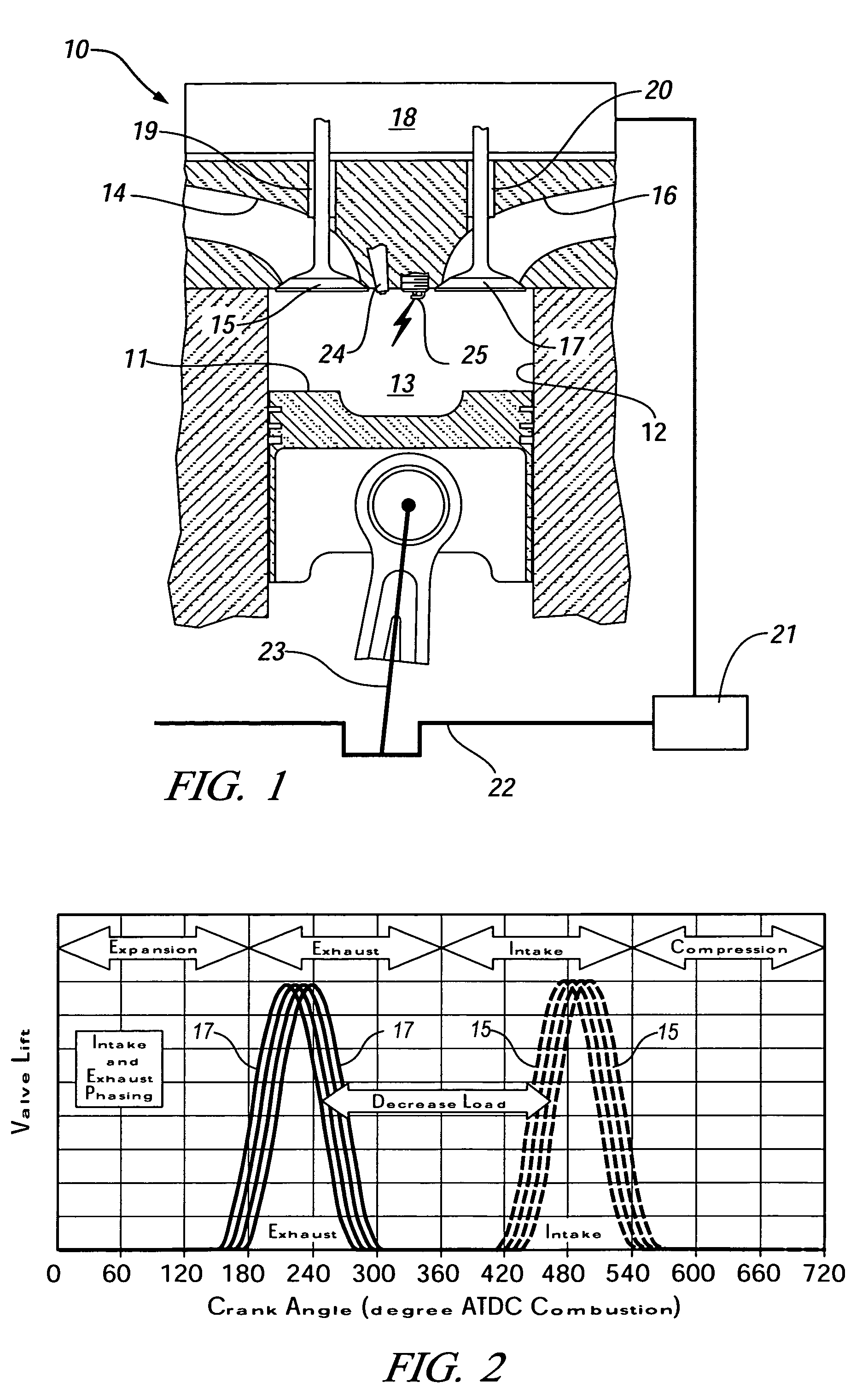
[0036]For simplicity, the following descriptions will address the present invention in its application to a single cylinder direct-injection gasoline four-stroke internal combustion engine, although it should be appreciated that the present invention is equally applicable to a multi-cylinder direct-injection gasoline four-stroke internal combustion engines. A four-stroke, single cylinder, 0.55 liter, internal combustion engine was utilized in implementing the various controls and acquisition of the various data embodied herein. Unless specifically discussed otherwise, all such implementations and acquisitions are assumed to be carried out under standard conditions as understood by one having ordinary skill in the art. The present invention is described in its application to a two valves per cylinder engine (one intake and one exhaust valve), although it should be appreciated that the present invention is equally applicable to a multi-valve per cylinder engine. And, although the pres...


PUM


Abstract

A direct injection controlled auto-ignition engine is operated at steady state, within a homogeneous charge compression-ignition (HCCI) load range and with fuel-air-diluent mixtures at predetermined conditions, for each speed and load, of engine control inputs, including at least injection timing (FI), spark timing (SI), throttle position, exhaust gas recirculation (EGR) valve setting and exhaust recompression obtained by negative valve overlap (NVO). During engine speed transients, the control inputs are synchronized to changes in the current engine speed, and also with any concurrent changes in the engine fueling rate. Inputs that are inactive during all or part of a speed change have a zero change rate while inactive. The method maintains robust auto-ignition combustion during speed transients with constant or variable fueling rates and with or without load changes.

Description

CROSS-REFERENCE TO RELATED APPLICATIONS[0001]This application claims priority from U.S. Provisional Patent Application No. 60 / 658,290 filed Mar. 3, 2005.TECHNICAL FIELD[0002]This invention relates to controlled auto-ignition internal combustion engines. More particularly, the invention is concerned with stability in speed transitions in such engines.BACKGROUND OF THE INVENTION[0003]To improve thermal efficiency of gasoline internal combustion engines, dilute combustion—using either air or re-circulated exhaust gas—is known to give enhanced thermal efficiency and low NOx emissions. However, there is a limit at which an engine can be operated with a diluted mixture because of misfire and combustion instability as a result of a slow burn. Known methods to extend the dilution limit include 1) improving ignitability of the mixture by enhancing ignition and fuel preparation, 2) increasing the flame speed by introducing charge motion and turbulence, and 3) operating the engine under contro...

Claims


Application Information

Patent Timeline
Patent Type & Authority Patents(United States)
IPC IPC(8): F02D43/00
CPCF02D13/0219F02D13/0265F02D37/02F02D41/3035F02D41/3064F02D41/402F02M25/0715F02M25/0752F02B1/12F02B23/101F02B2075/125F02D41/0002F02D41/005F02D41/2416F02D41/401F02D2041/141Y02T10/128Y02T10/44Y02T10/123Y02T10/18F02M26/13F02M26/01Y02T10/12Y02T10/40
Inventor CHANG, CHEN-FANGSUN, ZONGXUANKANG, JUN-MOKUO, TANG-WEIENG, JAMES A.BROWN, BARRY L.NAJT, PAUL M.CHANG, MAN-FENG
Owner GM GLOBAL TECH OPERATIONS LLC
Why Eureka
Try Eureka