Curved cochlear implant electrode array

a cochlear implant and electrode array technology, applied in external electrodes, ear treatment, artificial respiration, etc., can solve the problems of conductive hearing loss, impeded normal mechanical pathways for sound to reach the hair cells in the cochlea, and deafness sensorineural hearing loss

Inactive Publication Date: 2008-05-06
COCHLEAR LIMITED
View PDF27 Cites 25 Cited by
  • Summary
  • Abstract
  • Description
  • Claims
  • Application Information

AI Technical Summary

Benefits of technology

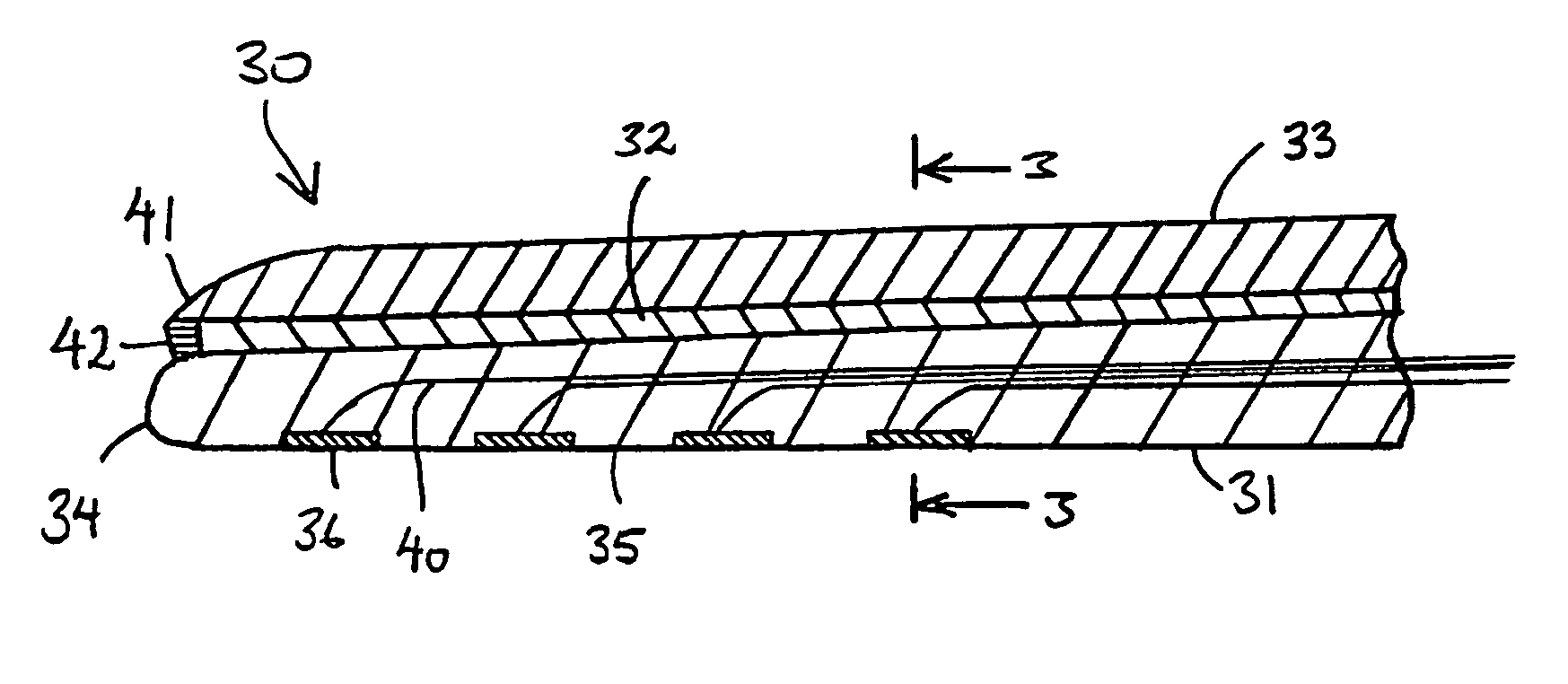
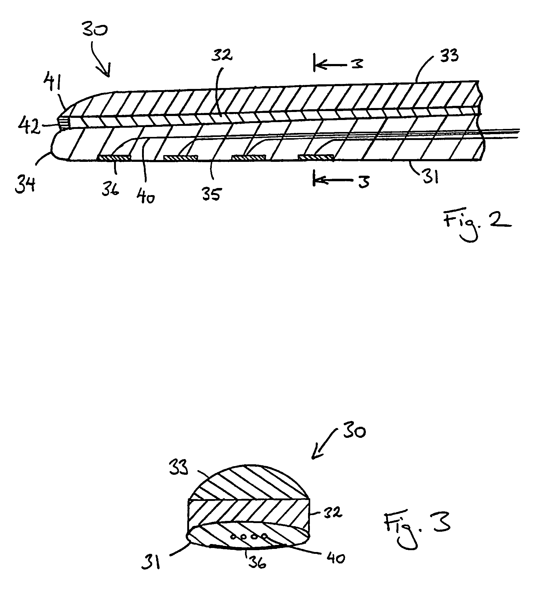
[0083]As the adhesive layer softens and becomes more lubricious, the outer layer gradually begins to move towards it natural curved configuration. As it curves, the outer layer pushes on the resiliently flexible carrier bringing it closer to the inner wall of the cochlea. The degree of curvature of the outer layer is preferably such that the final resting position of the carrier is against the modiolus but without exerting any or excessive pressure on the modiolus.

Problems solved by technology

Of these, conductive hearing loss occurs where the normal mechanical pathways for sound to reach the hair cells in the cochlea are impeded, for example, by damage to the ossicles.
In many people who are profoundly deaf, however, the reason for their deafness is sensorineural hearing loss.
These people are thus unable to derive suitable benefit from conventional hearing aid systems, no matter how loud the acoustic stimulus is made, because there is damage to or absence of the mechanism for nerve impulses to be generated from sound in the normal manner.
Moreover, the current from each electrode may flow in all directions, and the electrical fields corresponding to adjacent electrodes may overlap, thereby causing cross-electrode interference.
This is a challenge as the assembly needs to be shaped such that it assumes a curved shape to conform with the shape of the modiolus and must also be shaped such that the insertion process causes minimal trauma to the sensitive structures of the cochlea.

Method used


Image

  • Curved cochlear implant electrode array
  • Curved cochlear implant electrode array
  • Curved cochlear implant electrode array

Examples


Embodiment Construction

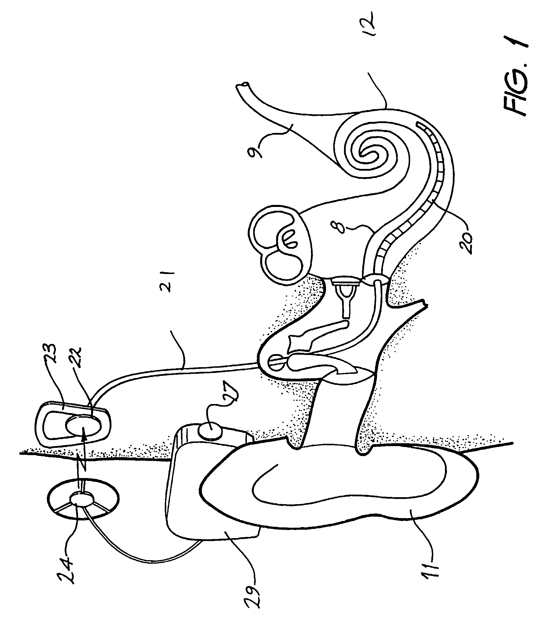
[0090]Before describing the features of the present invention, it is appropriate to briefly describe the construction of one type of known cochlear implant system with reference to FIG. 1.

[0091]Known cochlear implants typically consist of two main components, an external component including a speech processor 29, and an internal component including an implanted receiver and stimulator unit 22. The external component includes a microphone 27. The speech processor 29 is, in this illustration, constructed and arranged so that it can fit behind the outer ear 11. Alternative versions may be worn on the body. Attached to the speech processor 29 is a transmitter coil 24 that transmits electrical signals to the implanted unit 22 via a radio frequency (RF) link.

[0092]The implanted component includes a receiver coil 23 for receiving power and data from the transmitter coil 24. A cable 21 extends from the implanted receiver and stimulator unit 22 to the cochlea 12 and terminates in an electrod...


PUM


Abstract

An implantable electrode array (30) that can adopt a first, preferably straight, configuration selected to allow the array to be inserted into an implantee's body, such as the cochlea, and at least a second, preferably spirally curved, configuration where the electrode array is adapted to apply tissue stimulation to the cochlea. The array (30) includes an elongate carrier (31) having a proximal end and a distal end and a plurality of electrodes (36) supported by the carrier (31) at respective longitudinally spaced locations thereon. The array (30) further comprises an outer layer (33) adhered to the elongate carrier (31) by an intermediate bioresorbable adhesive layer (32) positioned at least partially between the carrier (31) and the outer layer (33). The outer layer (33) is shaped so as to normally preferentially adopt the second configuration, while the bioresorbable adhesive layer (32) has a configuration selected for biasing the array (30) into the first configuration prior to insertion of the array (30) into the cochlea. A method of forming the array (30) is also disclosed.

Description

CROSS-REFERENCE TO RELATED APPLICATION[0001]This application is a National Phase Patent Application of International Application Number PCT / AU02 / 00272, filed on Mar. 11, 2002, which claims priority of Australian Patent Application Number PR 3646, filed on Mar. 12, 2001.FIELD OF THE INVENTION[0002]The present invention relates to an implantable device and, in particular, to an implantable cochlear electrode assembly. A method of manufacturing such a device is also described.BACKGROUND OF THE INVENTION[0003]Hearing loss, which may be due to many different causes, is generally of two types, conductive and sensorineural. Of these, conductive hearing loss occurs where the normal mechanical pathways for sound to reach the hair cells in the cochlea are impeded, for example, by damage to the ossicles. Conductive hearing loss may often be helped by use of conventional hearing aids, which amplify sound so that acoustic information does reach the cochlea and the hair cells.[0004]In many people...

Claims


Application Information

Patent Timeline
Patent Type & Authority Patents(United States)
IPC IPC(8): A61F2/18A61F11/04A61N1/05A61N1/36H04R25/00
CPCA61N1/0541A61N1/36032A61N1/36039
Inventor DADD, FYSH
Owner COCHLEAR LIMITED
Why Eureka
Try Eureka