
Wireless portable automated harness scanner system and method therefor

a scanner and wireless technology, applied in the direction of electrical testing, instruments, transmission, etc., can solve the problems of complex or multiple connections, inconvenient methods, and difficult identification and location of electrical problems within wiring harnesses, and achieve the effect of reducing the time and the cost of the testing procedur

Active Publication Date: 2008-05-06
ZIOTA TECH
View PDF39 Cites 39 Cited by
  • Summary
  • Abstract
  • Description
  • Claims
  • Application Information

AI Technical Summary

Benefits of technology

The system enables efficient, cost-effective testing of wiring harnesses by allowing simultaneous testing of multiple lines, reducing human error, and providing accurate, automated documentation and analysis, facilitating quicker identification and repair of electrical issues.

Problems solved by technology

Therefore, electrical problems within a harness are incredibly hard to identify and locate, especially for already installed harnesses.
Unfortunately, such a method is inconvenient as it presents numerous drawbacks.
With prior art methods, the operators have to ring cables, one at a time, which requires many operators for complex or multiple connections.
However, such a method requires installation of interface cables and other components from the system for testing.
Additionally, it requires the deployment of many operators and the use of maintenance manuals, which makes the process time-consuming, expensive and prone to human error.
Another problem in the prior art is that of keeping accurate records of the results of testing and maintenance procedures.
Currently, such information is manually recorded by operators into wiring diagrams and / or work orders, a practice which is prone to errors and omissions and which does not allow for analysis of the data recorded over time.
Unfortunately, prior art TDR methods do not allow for performing testing on multiple wires at a time, which proves to be time consuming and does not allow for gathering complete and accurate information regarding the wires.

Method used


Image

  • Wireless portable automated harness scanner system and method therefor
  • Wireless portable automated harness scanner system and method therefor
  • Wireless portable automated harness scanner system and method therefor

Examples


Embodiment Construction

[0025]As illustrated in FIG. 4, the present invention is a fully portable automated test system allowing verification of any type of installed wiring harness 27 using a new open platform architecture for the transport industry. Even though the testing system shown in FIG. 4 is used for testing a wiring harness installed in a plane, the testing system could also be used for testing a wiring harness installed in any other installation for which periodical testing, diagnosis and maintenance is required. Such other installations might include, but are not limited to, boats, ships, trains, cars, etc.

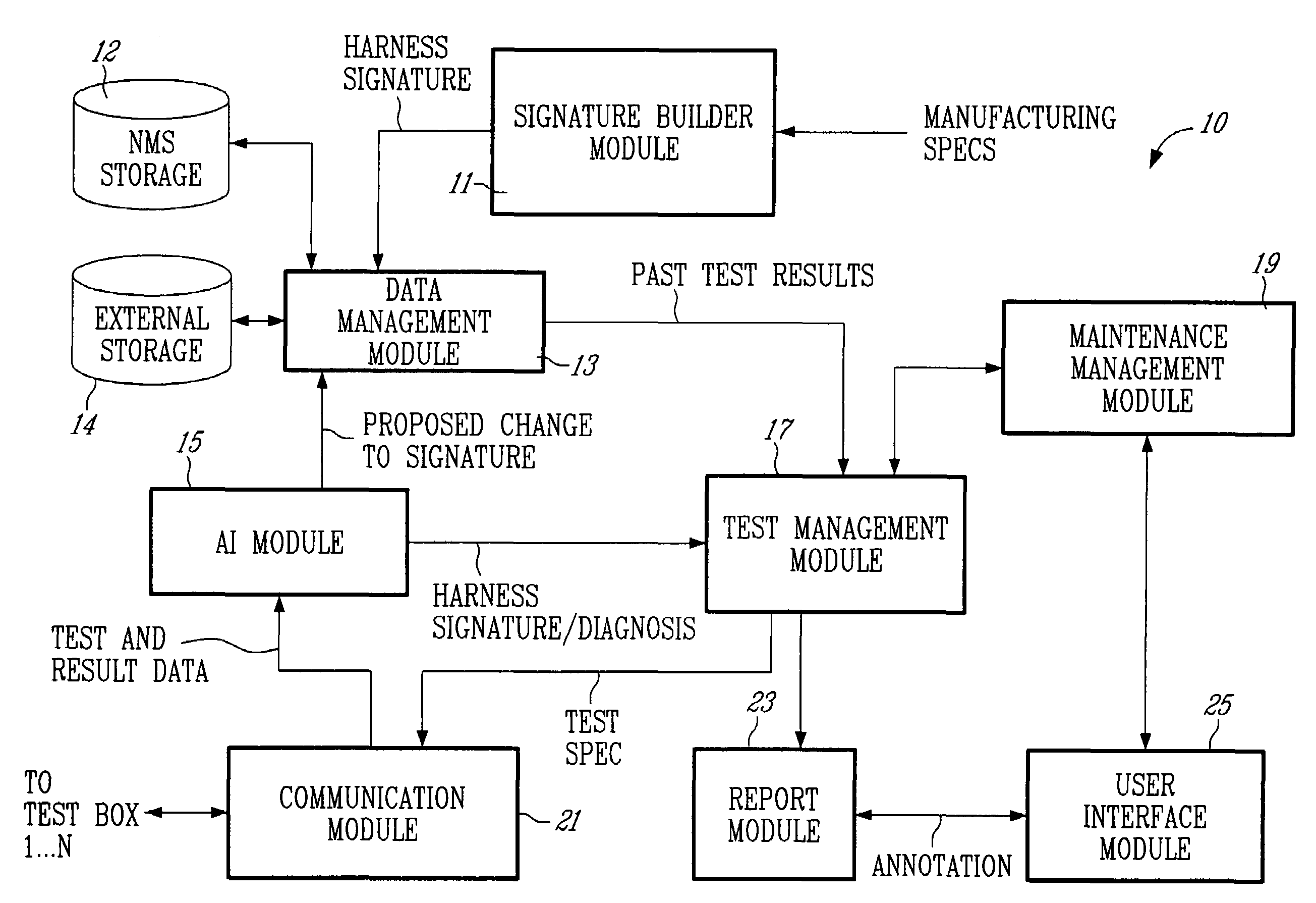
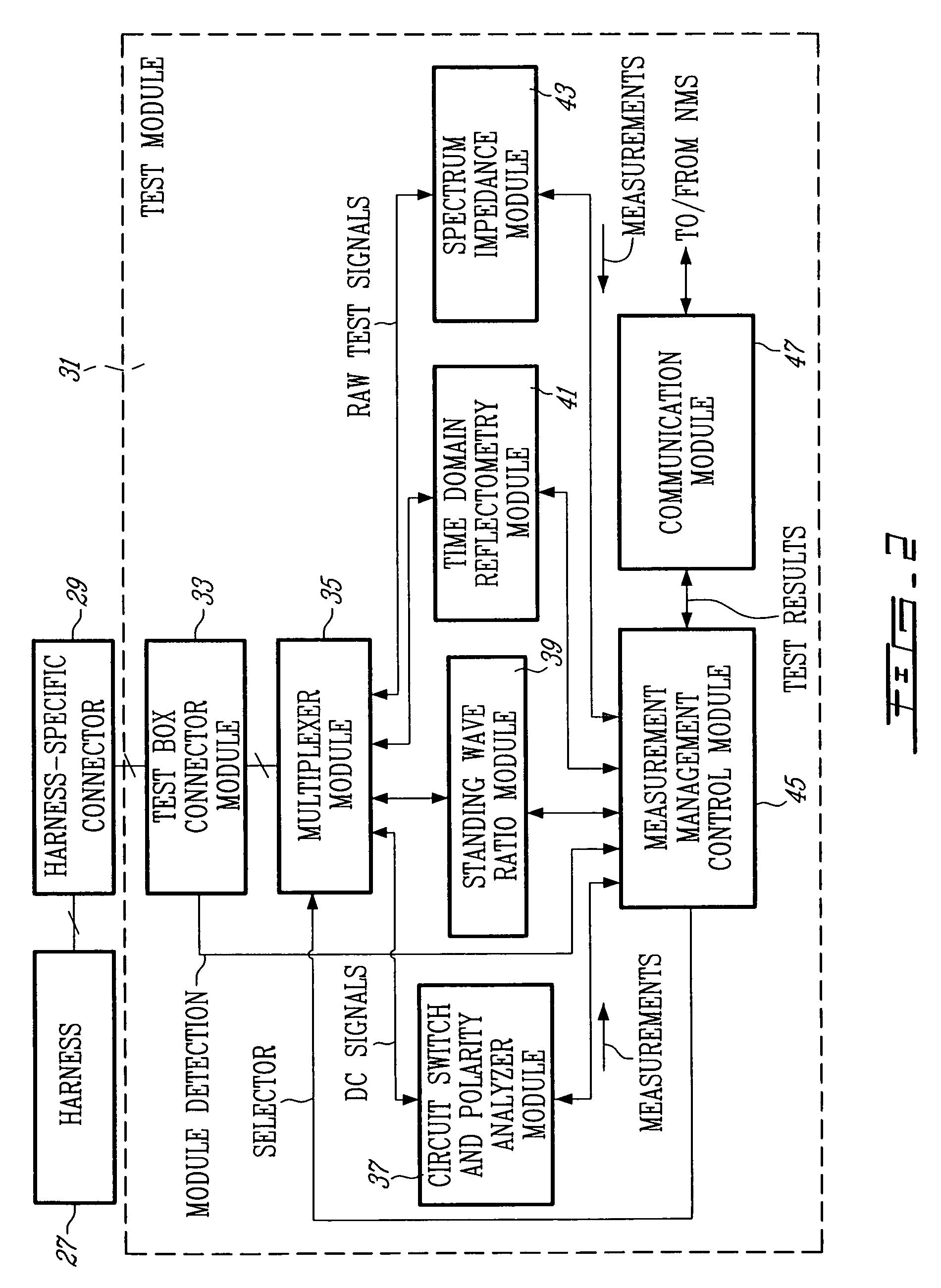
[0026]In the preferred embodiment of the present invention, the automated testing system is a distributed network, comprising a plurality of test modules 31 which are connected to the wiring harness 27 at the location of existing harness connectors 29. The test modules 31 are in communication with a central Network Management System (NMS) 10, from which the test modules 31 receive information...


PUM


Abstract

A method for testing an installed wiring harness is provided. The method comprises providing a signal source testing module at a first node in the wiring harness and a measurement termination testing module at a second node in the wiring harness. A central management module for controlling the testing modules coordinates the testing modules to send testing signals for performing tests and recording test measurements of the installed wiring harness. The testing modules send the test measurements to the management module.

Description

CROSS REFERENCE TO RELATED APPLICATIONS[0001]This is the first application for this invention.FIELD OF THE INVENTION[0002]The invention relates to a system and method for testing and repairing installed wiring harnesses.BACKGROUND OF THE INVENTION[0003]An electrical wiring harness typically comprises a bundle of individual connector wires of varying gauges, impedances and types, all arranged and distributed at different locations within an installation, such as a transport vehicle. Such wiring harnesses are usually bound together in order to facilitate the installation, repair and maintenance of the wires. The transport vehicle industry, especially the aviation and the automobile industries, makes extensive use of such wiring assemblies.[0004]In the aircraft industry, wiring harnesses are used to interconnect the various components and subassemblies located within an aircraft. The number of possible electrical interconnections within a harness grows exponentially with the number of ...

Claims


Application Information

Patent Timeline
Patent Type & Authority Patents(United States)
IPC IPC(8): G01R31/02H04B3/46
CPCG01R31/021G01R31/008G01R31/11G01R31/086G01R31/58
Inventor GERVAIS, FRANCOIS
Owner ZIOTA TECH
Learn More