Power amplifier with low power distortion at output

a power amplifier and output technology, applied in the field of digital/analog amplifiers, can solve the problems of distortion increase, parity harmonics, drawback of introducing distortion into the output signal at the terminal of the load of the amplifier,

Inactive Publication Date: 2008-05-06
ST ERICSSON SA
View PDF3 Cites 9 Cited by
  • Summary
  • Abstract
  • Description
  • Claims
  • Application Information

AI Technical Summary

Benefits of technology

[0009]In view of the foregoing background, an object of the present invention is to provide an approach to the problem described above that is easier to implement.
[0011]A parasitic capacitive circuit, which is inherent in the power inverter and which it is commonly sought to avoid, has a surprisingly beneficial effect on the distortion caused by the dead time in the output signal of the amplifier. It is useful to increase the capacitance of the parasitic capacitive circuit to augment this beneficial effect, and thus eliminate the distortion caused by the dead time.
[0013]Study of the output signals of the amplifier has shown that a capacitive circuit Cout at the output of the amplifier generates a square-wave signal that is expressed in frequency by a sine signal with added odd-parity harmonics (this can be seen by a Fourier series decomposition), and that these odd-parity harmonics counter the harmonics introduced by the dead time and attenuate them, or even make them disappear so that the distortion of the output signal disappears.

Problems solved by technology

While this lag has the advantage of preventing short-circuiting of the power supply, it has the drawback of introducing a distortion into the output signal at the terminals of the load of the amplifier in the form of odd-parity harmonics.
The distortion increases with the dead time and with the frequency of the switch-over of the transistors of the power inverters of the amplifier.
However, the dead time cannot be eliminated, and the distortion that it introduces cannot be eliminated either.
However, this approach is difficult to implement because it is difficult to apply a delay equal to the dead time, especially when the dead time is small.
This approach is very efficient but providing a negative feedback loop is difficult and costly.

Method used


Image

  • Power amplifier with low power distortion at output
  • Power amplifier with low power distortion at output

Examples


Embodiment Construction

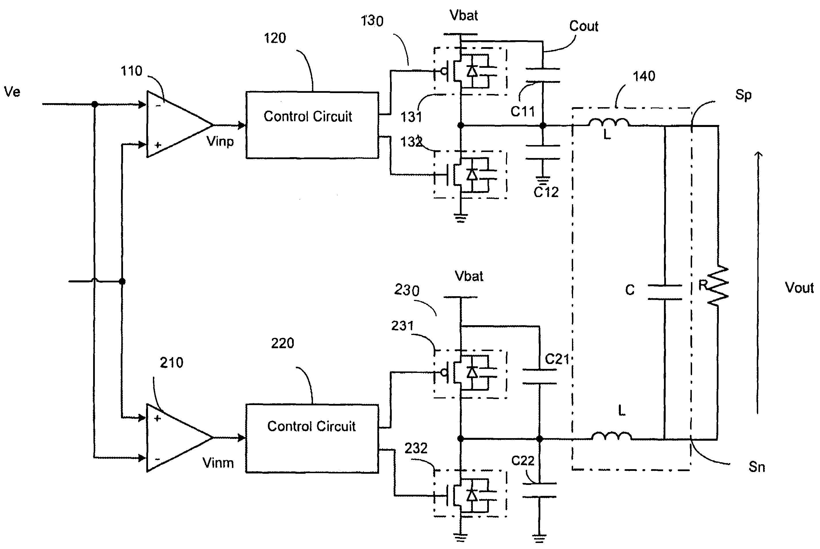
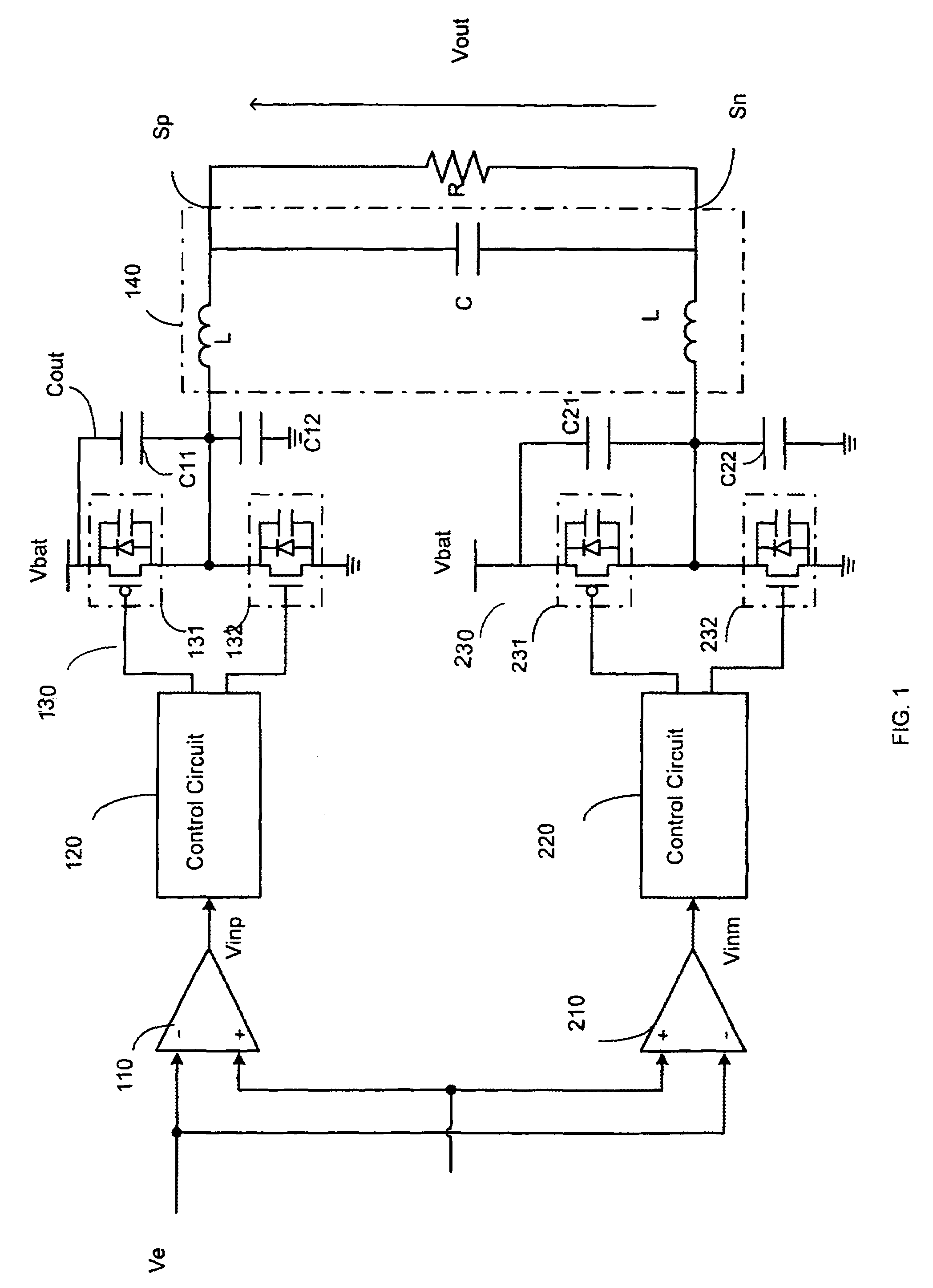
[0015]A digital / analog amplifier typically comprises an arm in which the following are associated in series: a pulse-width modulator PWM 110, a control circuit 120, a power inverter 130 and a filter 140. The filter 140 in this case is an LC type filter. The inverter 130 has a P-type power transistor 131 and an N-type power transistor 132 series-connected between a power supply terminal to which a power supply potential Vbat is applied and a ground of the amplifier.

[0016]In the example shown in FIG. 1, the amplifier is a differential amplifier and comprises two arms as described above, one called PLUS and the other called MINUS. If the amplifier is a D-class amplifier, a differential assembly gives an output power equal to four times the power of a non-differential amplifier. Thus, amplifiers capable of achieving efficiency levels of about 90% are obtained.

[0017]In one exemplary application, the amplifier is used to amplify audio type signals Ve with a frequency ranging from 0 to 24 ...


PUM


Abstract

A digital / analog amplifier includes the following coupled in series: a pulse-width modulator, a control circuit, a power inverter and a filter. The power inverter comprises two transistors series-connected between a power supply terminal and a ground of the amplifier. The control circuit drives the transistors of the power inverter. One output of the filter forms an output of the amplifier to which a load is connected. The amplifier also comprises a capacitive circuit parallel-connected to the output of the power inverter.

Description

FIELD OF THE INVENTION[0001]The present invention relates generally to power amplifiers, and more specifically, to a digital / analog amplifier.BACKGROUND OF THE INVENTION[0002]A digital / analog amplifier of this kind, for example, is commonly used as a D-class amplifier for audio applications, especially embedded applications. This is due to the fact that they have very high rates of efficiency.[0003]The signal to be amplified is pulse-width modulated. The control circuit produces drive signals for the transistors of the inverter as a function of the modulated signal. The output of the inverter is applied to the input of the filter, and a sine signal is recovered at the output of the filter. The output of the amplifier, formed by the output of the filter, is connected to the terminals of a load that is a resistor formed by the impedance of an audio loudspeaker, for example.[0004]Preferably, to obtain optimum efficiency, a differential amplifier is provided. This differential amplifier...

Claims


Application Information

Patent Timeline
Patent Type & Authority Patents(United States)
IPC IPC(8): H03F3/38
CPCH03F1/32H03F3/217H03F2200/351
Inventor PILLONNET, GAEL
Owner ST ERICSSON SA
Why Eureka
Try Eureka