Optical projection system and image display device having the same

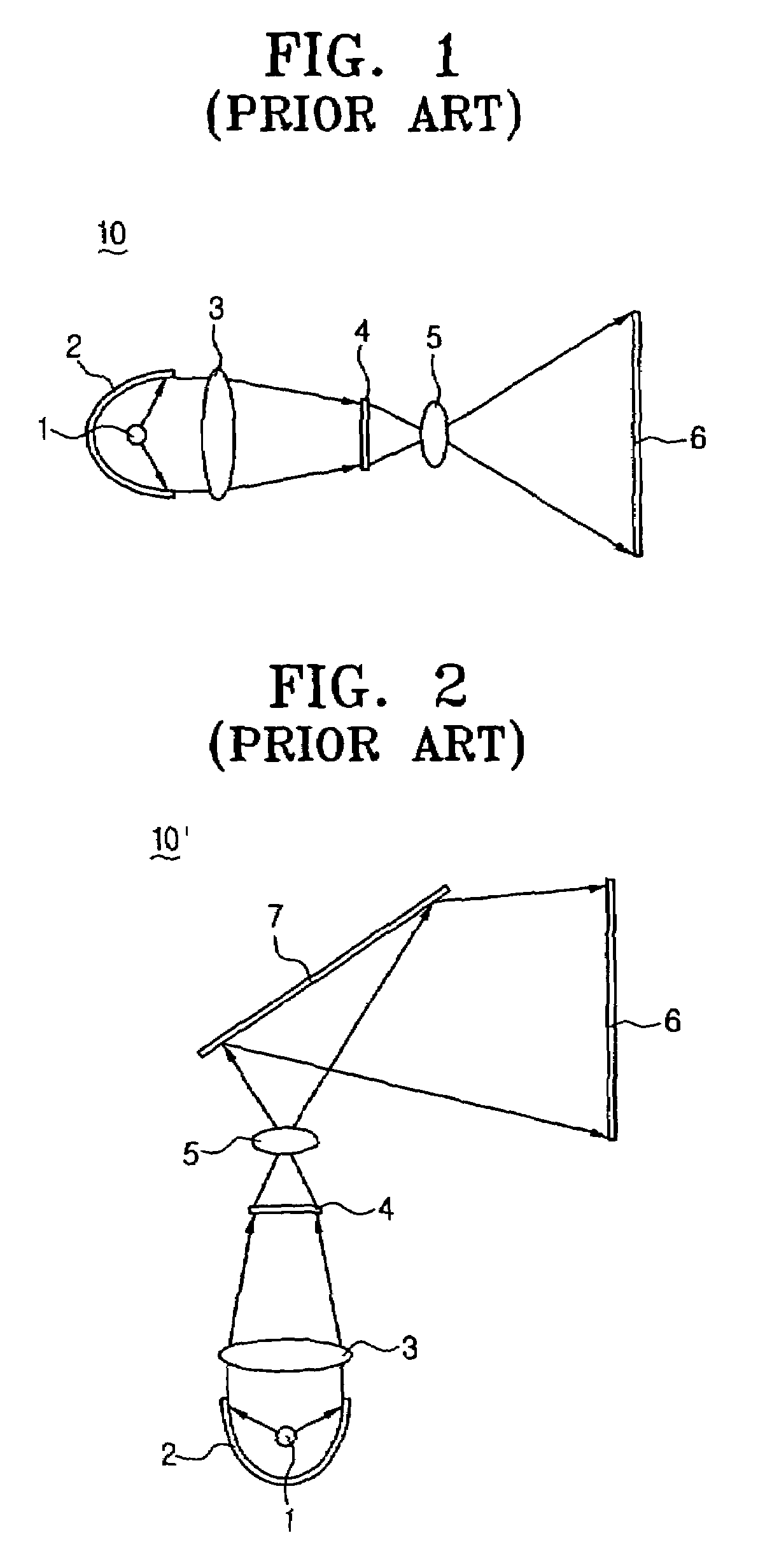
a projection system and optical technology, applied in the field of optical projection system and image display device, can solve the problems of reducing the depth of the conventional projection television b>10/b> using the wide-angle projection optical lens, affecting the image, and affecting the image, so as to achieve the effect of reducing the depth of the image display devi

Inactive Publication Date: 2008-05-13
SAMSUNG ELECTRONICS CO LTD
View PDF11 Cites 11 Cited by
  • Summary
  • Abstract
  • Description
  • Claims
  • Application Information

AI Technical Summary

Benefits of technology

[0016]The present general inventive concept provides an optical projection system and an image display device having the same, which projects an image by a large angle of view onto a screen by vertically arranging the optical projection system and having a refraction part and a reflection part. Thus, a depth of the image display device is reduced, and light beams emitted from a lighting system and a micro display part do not interfere with the image projected onto the screen.
[0017]The present general inventive concept also provides an optical projection system and an image display device having the same, which is capable of compensating for distortion in an image using characteristics of an aspheric lens so that a large image of superior quality can be obtained.
[0018]The present general inventive concept also provides an optical projection system and an image display device having the same, which bends a path of light from a horizontal direction to a vertical direction such that a depth of the image display device is reduced and compact, thereby minimizing a size thereof.

Problems solved by technology

However, since the wide-angle projecting optical lens used to increase an angle of view has limitations, decreasing the depth of the conventional projection television 10 using the wide-angle projection optical lens also has limitations.
As such, the depth decreases more than the conventional projection television 10, however, an image projected back by the flat reflecting mirror 7 may tend to interfere with the image formed by the light valve 4 and projected from the lighting system.
As a result, the image gets grainy or dim.

Method used


Image

  • Optical projection system and image display device having the same
  • Optical projection system and image display device having the same
  • Optical projection system and image display device having the same

Examples


Embodiment Construction

[0038]Reference will now be made in detail to the embodiments of the present general inventive concept, examples of which are illustrated in the accompanying drawings, wherein like reference numerals refer to the like elements throughout. The embodiments are described below in order to explain the present general inventive concept by referring to the figures.

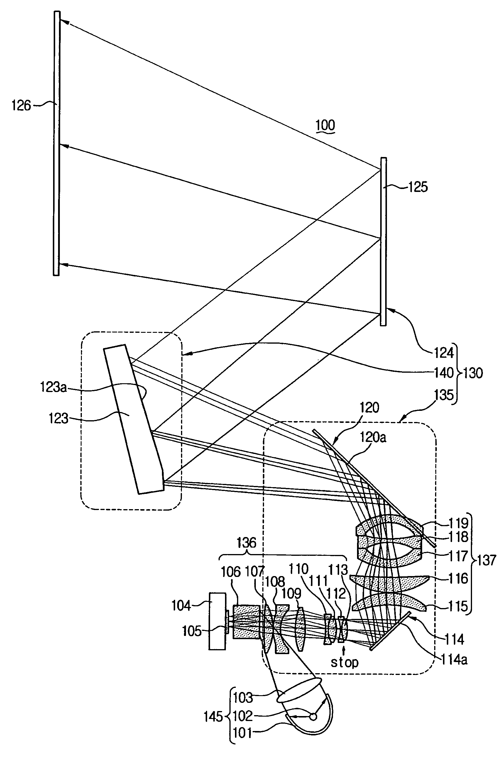
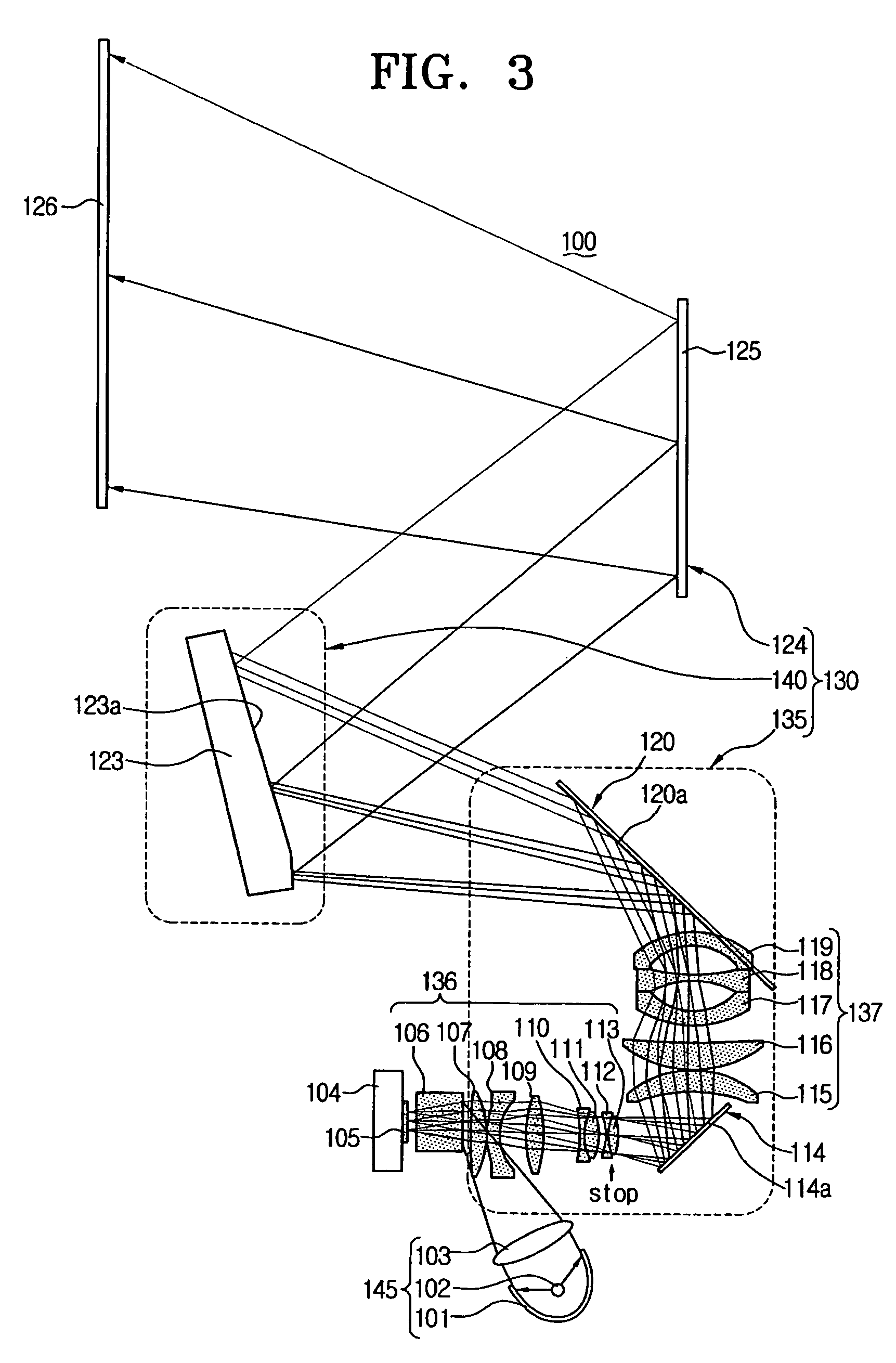
[0039]FIG. 3 illustrates an image display device 100 (e.g., a projection television) including an optical projection system according to an embodiment of the present general inventive concept.

[0040]The image display device 100 comprises a lighting system 145 to radiate light beams, a micro display part 104 to modulate the light beams according to an electric image signal to generate an image therefrom and to project the image, an optical projection system 130 to enlarge the projected image and to form an enlarged image (c) without distortion (see FIG. 4C) and to project the enlarged image (c) onto a screen 126, and the screen 12...


PUM


Abstract

An optical projection system which creates pincushion distortion of an image and then creates a barrel distortion of the pincushion-distorted image to compensate for the pincushion distortion and then projects an enlarged image without substantial distortion onto an image display surface. An embodiment includes a polynomial reflector to compensate for the pincushion distortion, to enlarge an image, and to project the enlarged image toward a screen.

Description

CROSS-REFERENCE TO RELATED APPLICATIONS[0001]This application claims the benefit of Korean Patent Application No. 2004-8454 filed on Feb. 9, 2004, in the Korean Intellectual Property Office, the disclosure of which is incorporated herein by reference in its entirety.BACKGROUND OF THE INVENTION[0002]1. Field of the Invention[0003]The present general inventive concept relates to an image display device, such as a projection television. More particularly, the present general inventive concept relates to an optical projection system, which has a compact depth and an image display device having the same.[0004]2. Description of the Related Art[0005]An image display device, such as a projection television, generates an image using a micro display, and enlarges the image via an optical projection system to project the image onto a large-sized screen. Consumer demand for the image display device having the large-sized screen has recently increased.[0006]FIG. 1 illustrates a conventional proj...

Claims


Application Information

Patent Timeline
Patent Type & Authority Patents(United States)
IPC IPC(8): G03B21/14G02B15/14G03B21/22G03B21/20G02B17/00H04N5/74G02B17/08G02B27/18G03B21/00H04N9/31
CPCG02B17/08G02B17/0852G03B21/14G03B21/147G03B21/28H04N5/74
Inventor LEE, JONG-SOO
Owner SAMSUNG ELECTRONICS CO LTD
Why Eureka
Try Eureka