Illuminated dental examination instrument

a dental examination and illumination technology, applied in the field of medical diagnostic instruments, can solve the problems of complicated overall design and manufacture of instruments, including cost, and achieve the effects of improving optical coupling, increasing illumination output, and convenient for caregivers

Inactive Publication Date: 2008-05-13
INTEGRA YORK PA
View PDF29 Cites 10 Cited by
  • Summary
  • Abstract
  • Description
  • Claims
  • Application Information

AI Technical Summary

Benefits of technology

[0015]An advantage of the present invention is that the reflector of the LED housing is raised above the LED lens envelope so as to protect the at least one LED from impact and / or shock loads or other damage that can occur, for example, during shipping, handling of the instrument, and during disassembly when removing the batteries.
[0016]Yet another advantage provided by the reflector of the present invention is improved optical coupling between the at least one LED and the mirror, thereby increasing illumination output.
[0017]Yet another advantage provided by the present invention is that the present instrument is cordless, and is therefore quite convenient for the caregiver (e.g., dentist or hygienist) to utilize, the instrument preferably being conveniently powered by a set of rechargeable batteries.
[0018]Still another advantage of the present invention is that less heat is generated using at least one LED as an illumination source rather than an incandescent bulb while producing sufficient illumination for examination purposes.
[0019]Still another advantage of the present instrument is that it can be easily disassembled so that the batteries and illumination housing can be set aside, allowing the handle portions can be autoclaved (e.g., sterilized).

Problems solved by technology

One problem encountered in the use of incadescent bulbs as an illumination source in instruments, such as those described above, relates to heat generation developing from the contained bulb, thereby requiring the placement of suitable heat sinks or other heat dissipation means in the instrument and / or the use of open slotted vents in the gripping handle thereof.
These solutions to the above problem complicate the overall design and manufacture of the instrument, including the cost thereof.
A problem in using these light sources, however, has been in achieving sufficient illumination output for purposes of examination.

Method used


Image

  • Illuminated dental examination instrument
  • Illuminated dental examination instrument
  • Illuminated dental examination instrument

Examples


Embodiment Construction

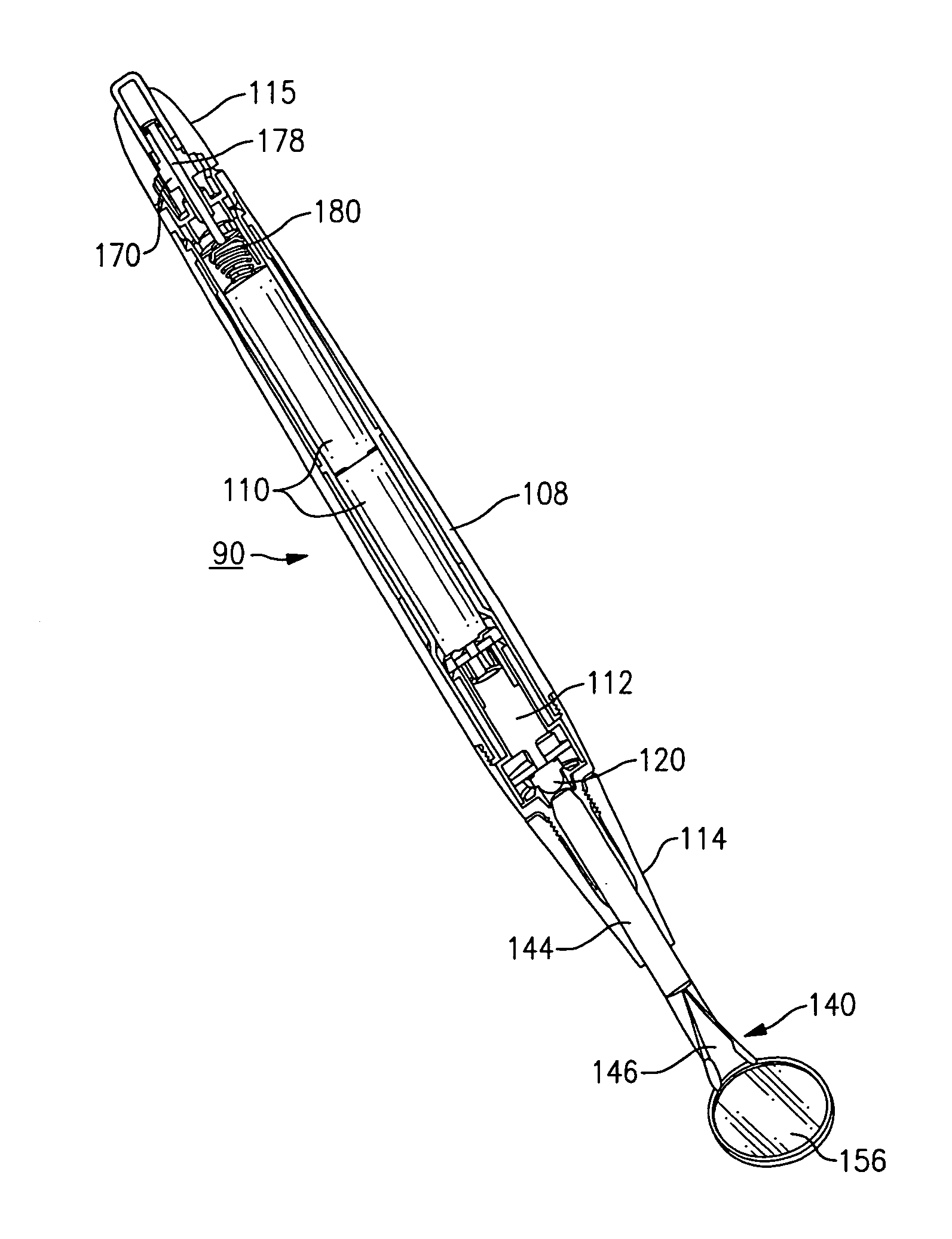
[0032]The following description relates to an intraoral dental examination instrument that is made in accordance with certain preferred embodiments of the present invention. Throughout the course of discussion that follows several terms, such as “top”, “side”, “lateral”, “bottom”, “distal”, “proximal”, “front”, “rear”, and the like are used in order to provide a convenient frame of reference with regard to the accompanying drawings. These descriptions, however, unless indicated otherwise, should not be regarded as limiting with regard to the present invention.

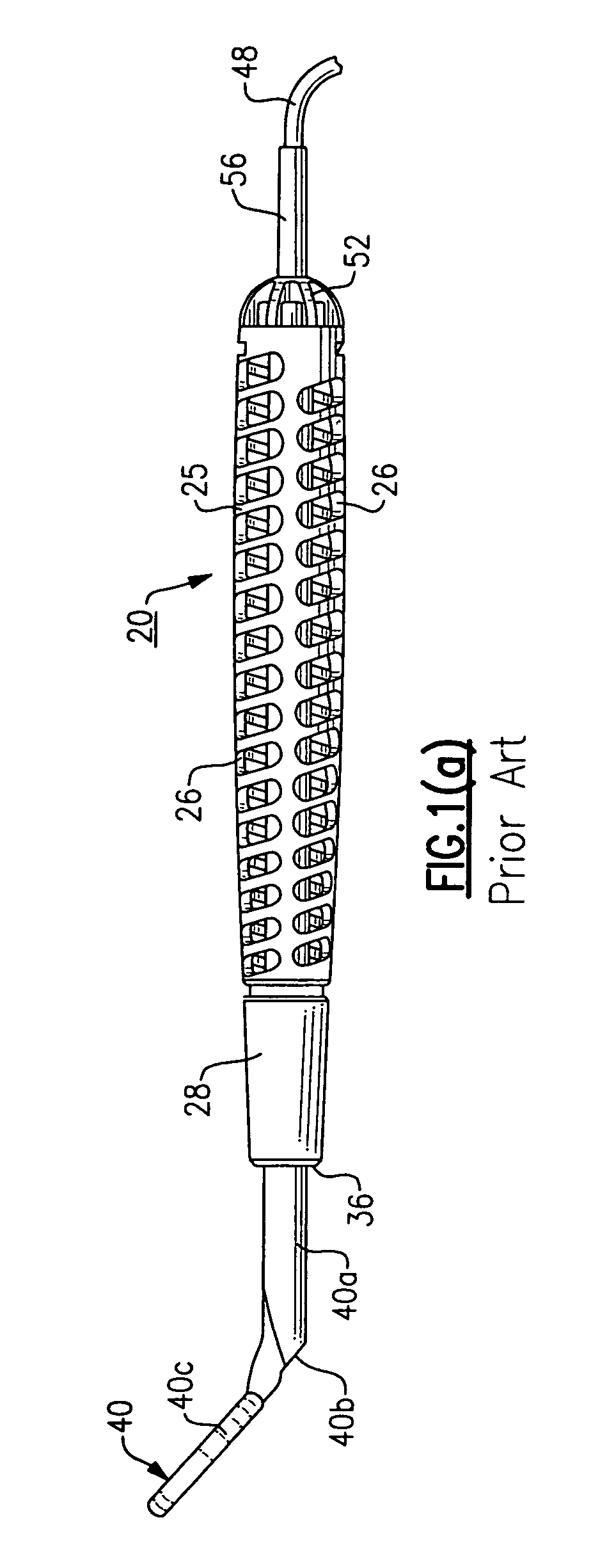
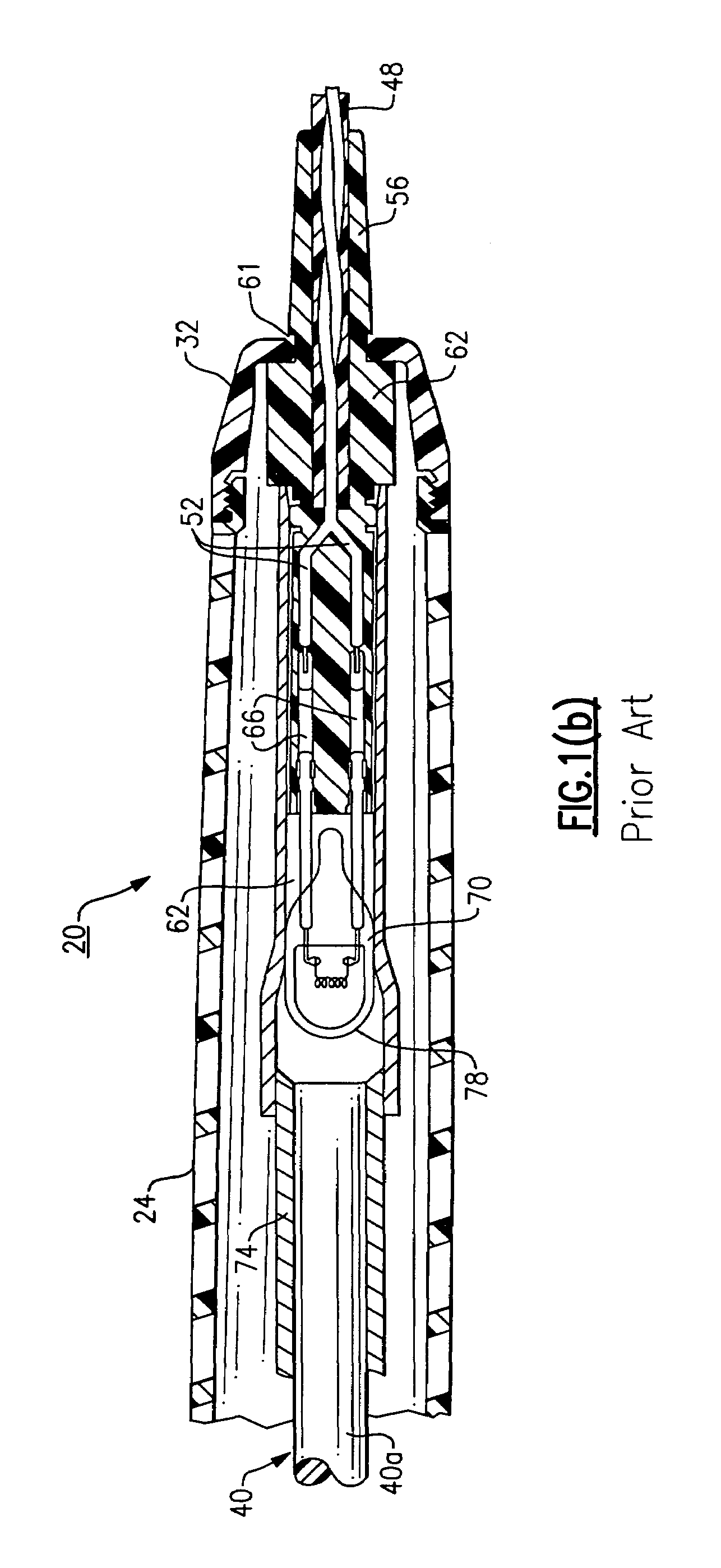
[0033]Prior to discussing the present invention and referring first to FIG. 1, there is illustrated an intraoral dental examination instrument 20 (partially shown according to the figure) that is made in accordance with the known art, described herein for background purposes. The examination instrument 20 is defined by an elongated body section 24, a front end cap 28 and a rear end cap 32, each preferably made from a moldable p...


PUM


Abstract

An intraoral dental instrument includes an elongate handle or body and a mirror that is releasably attachable to a distal end thereof. An LED housing disposed in the handle proximate a light entrance surface of the mirror includes a housing body sized to retain at least one LED and a reflector attached to a distal end of the housing body. The reflector has an inwardly tapered cavity covering a LED lens envelope for focusing illumination from the at least one LED onto a portion of the light entrance surface of the mirror.

Description

FIELD OF THE INVENTION[0001]This invention relates to the field of medical diagnostic instruments and more particularly to an improved design for mounting at least one LED in a medical diagnostic instrument so as to provide more effective illumination, for example, in an intraoral dental mirror.BACKGROUND OF THE INVENTION[0002]Intraoral dental mirrors are repletely known in the field of dentistry as convenient apparatus for aiding in the inspection of the teeth of a patient. Typically, these instruments include an elongated handle having a retroflexed mirrored portion that permits inspection of both the upper and lower arches of teeth. Illuminated versions of these devices typically include a halogen lamp or other similar miniature light source, such as described in U.S. Pat. Nos. 5,741,132 and 6,575,744B1, that is provided beneath the mirror in a retroflexed portion of the instrument, or as described in U.S. Pat. Nos. 5,139,421 and 5,457,611, to Verderber, in which a miniature halo...

Claims


Application Information

Patent Timeline
Patent Type & Authority Patents(United States)
IPC IPC(8): A61C3/00
CPCA61B1/247A61B1/00105A61B1/0684A61B1/0669
Inventor TAMBURRINO, RICHARD A.CONNELLY, JACK L.WOJNOWICZ, CATHERINE R.SCHWAGER, BRUCE H.YANG, DONGMINLIA, RAYMOND A.PERKINS, JEFFREY J.LESEBERG, ROGER W.MCMAHON, MICHAEL T.
Owner INTEGRA YORK PA
Why Eureka
Try Eureka