RF shield and method for fabricating the same

a technology of shield and shielding plate, which is applied in the direction of electrical apparatus casing/cabinet/drawer, ventilation panel with screening provisions, etc., can solve the problems of affecting the operation of electronic equipment. , to achieve the effect of preventing electromagnetic interference, and reducing the cost of operation

Inactive Publication Date: 2008-05-13
L 3 COMM CORP
View PDF9 Cites 69 Cited by
  • Summary
  • Abstract
  • Description
  • Claims
  • Application Information

AI Technical Summary

Problems solved by technology

For many years, it has been known that electro-magnetic fields, such as RF waves, can disrupt the operation of electronic equipment and cause electronic equipment to malfunction.
For example, the RF energy radiated from a nearby lightning strike, sometimes referred to as an electro-magnetic pulse (EMP), can disrupt sensitive electronic equipment or RF from a vacuum cleaner motor can disrupt a television.
However, metallic screens provide quite limited RF attenuation and are structurally weak.
Honeycomb shielding is still relatively delicate and is not strong enough to handle stresses in many circumstances, such as in a vibrating environment (e.g., a moving vehicle, a pulsating flow, etc.).
The principal disadvantages of “tube packs” are their fabrication complexity with all the joints having to be seam welded, the volume taken by the assembled “tube pack”, and in some cases the weight of the assembly.
Honeycomb panels are not structurally strong enough to hand hostile environments.
Tube packs can be structurally strong but require a considerable volume and weight allocation and are very expensive to fabricate.

Method used


Image

  • RF shield and method for fabricating the same
  • RF shield and method for fabricating the same
  • RF shield and method for fabricating the same

Examples


Embodiment Construction

[0026]While the present invention may be embodied in many different forms, a number of illustrative embodiments are described herein with the understanding that the present disclosure is to be considered as providing examples of the principles of the invention and such examples are not intended to limit the invention to preferred embodiments described herein and / or illustrated herein.

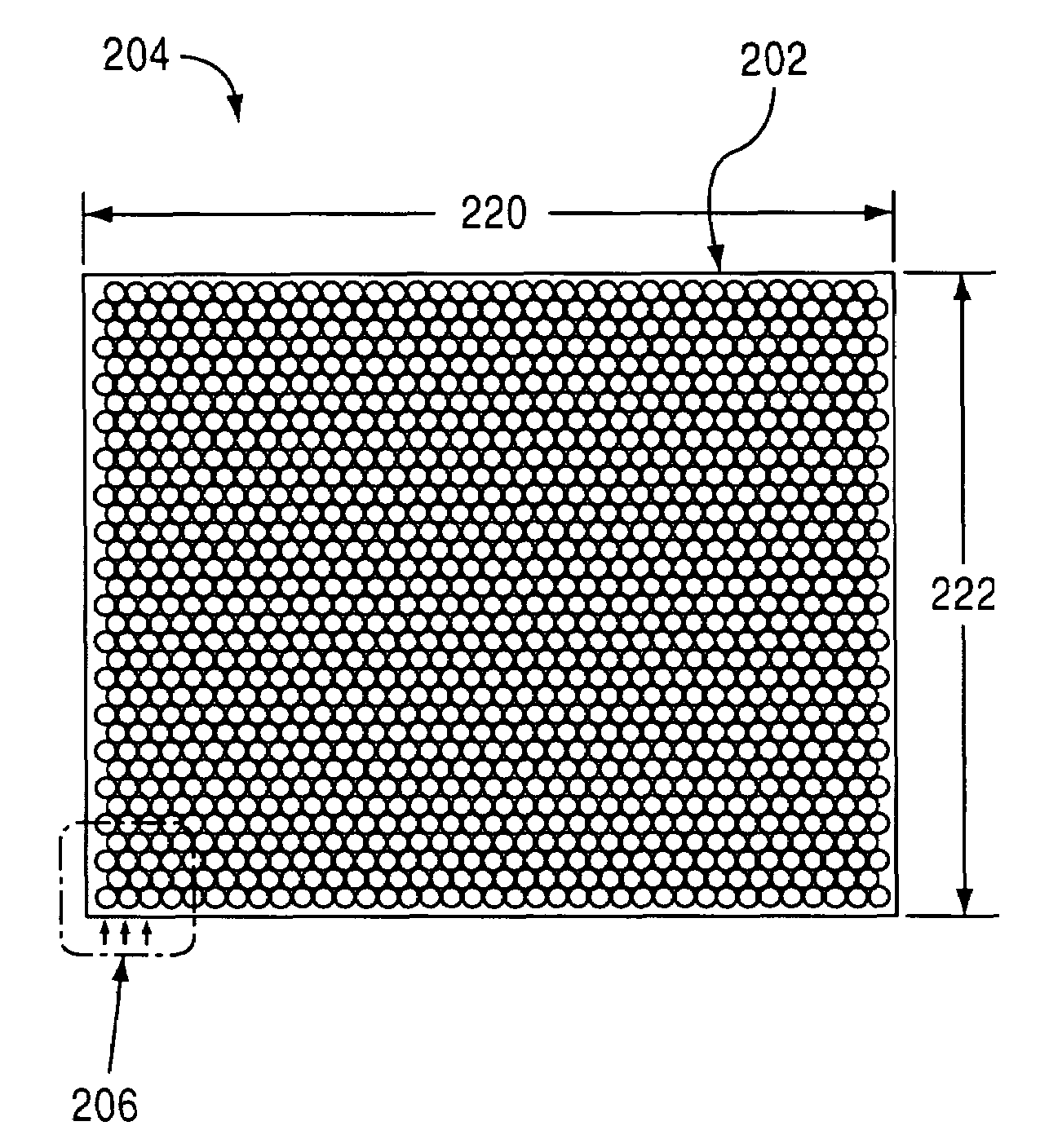
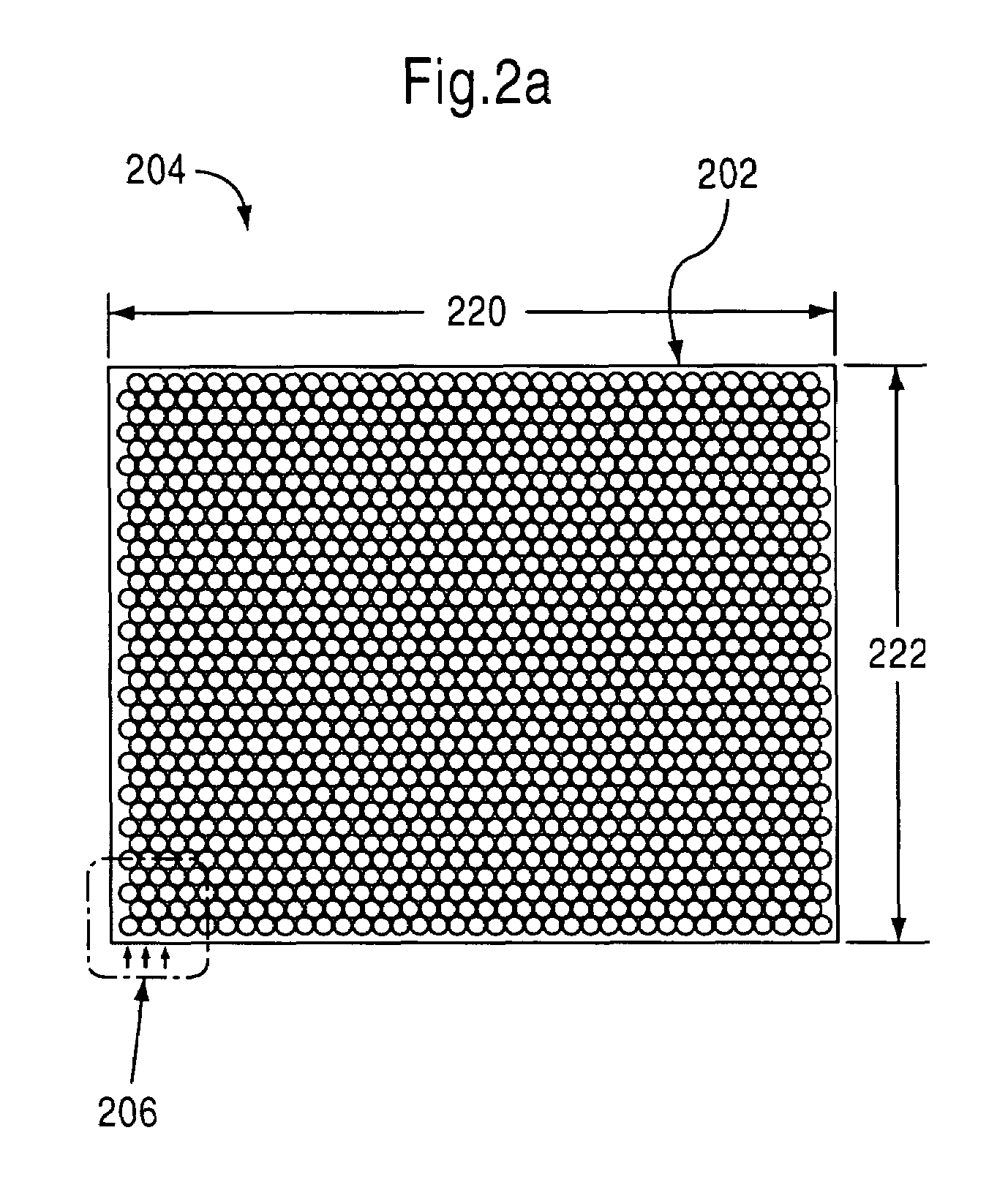
[0027]According to an embodiment of the present invention, an RF shield is provided that can be fabricated to be arbitrarily strong and is particularly useful for applications in hostile environments. RF shields according to the present invention are particularly useful in mobile apparatuses required to withstand harsh travel conditions.

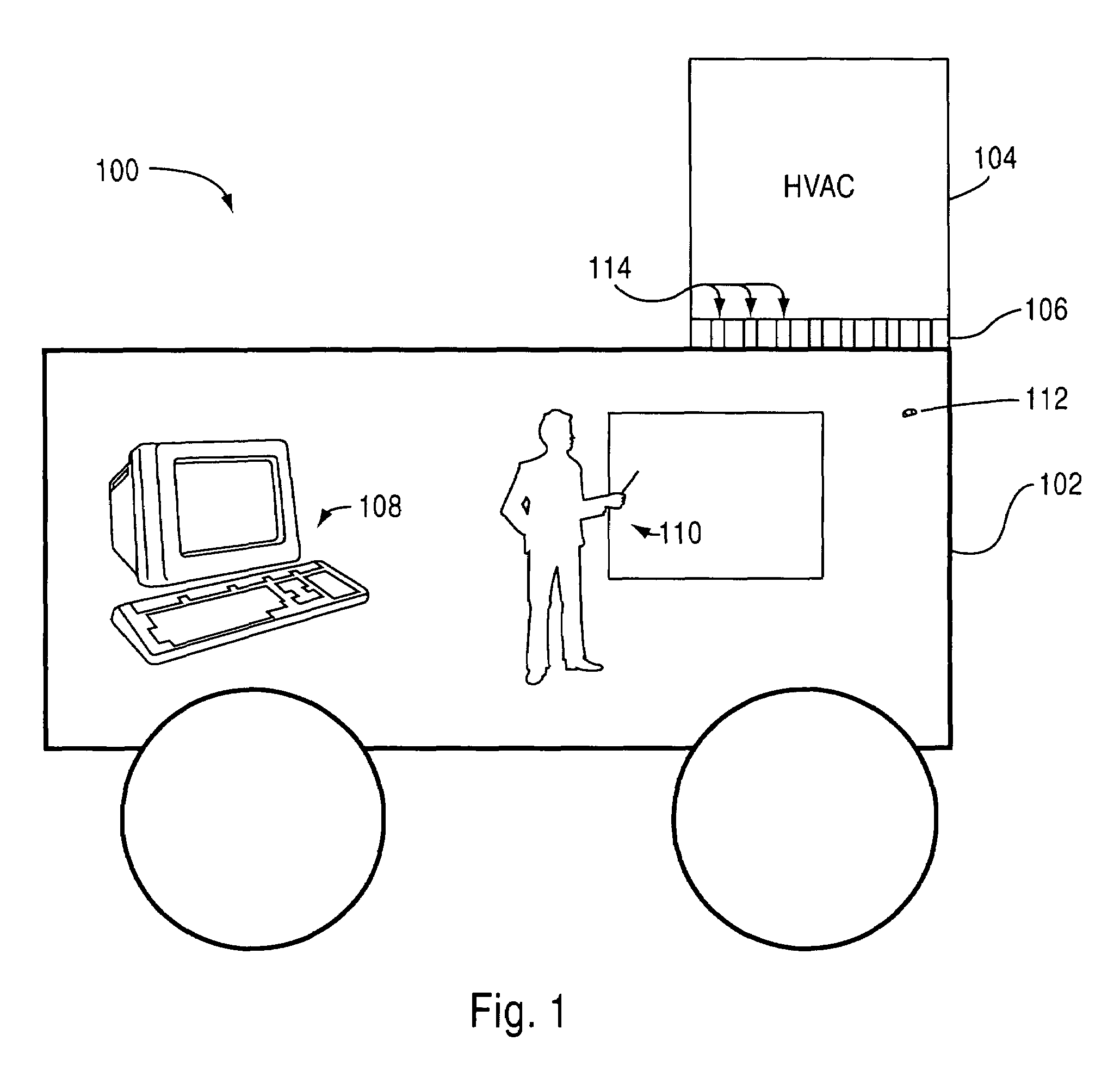
[0028]FIG. 1 is a diagram of a mobile apparatus with shielding. The mobile apparatus 100 houses computer equipment 108 and human operators 110. A solid exterior conductive wall 102 protects the computer equipment from external radiation, such as RF interference.

[0029]In ...


PUM

PropertyMeasurementUnit
diameteraaaaaaaaaa
thicknessaaaaaaaaaa
lengthaaaaaaaaaa

Abstract

An RF shield is fabricated from a solid piece of metal or metal alloy. Holes are cut through the metal or metal alloy at fixed positions to form an array. The diameter of the holes is selected to be significantly smaller than the RF wavelength (e.g., ⅓) it is designed to prevent from passing through the holes. The thickness of the plate (length of the holes) establishes the attenuation of the shield. The number of holes establishes the air or other fluid throughput.

Description

BACKGROUND OF THE INVENTION[0001]1. Field of the Invention[0002]The present invention relates generally to products and methods for preventing electro-magnetic interference. More particularly, the present invention relates to a conductive and arbitrarily strong radio frequency (RF) shield that protects electronic equipment from being disrupted by RF waves while also allowing for fluid or air flow therethrough, and a method for making the RF shield.[0003]2. Description of the Related Art[0004]For many years, it has been known that electro-magnetic fields, such as RF waves, can disrupt the operation of electronic equipment and cause electronic equipment to malfunction. For example, the RF energy radiated from a nearby lightning strike, sometimes referred to as an electro-magnetic pulse (EMP), can disrupt sensitive electronic equipment or RF from a vacuum cleaner motor can disrupt a television. It is well known that conductive shielding can be effective in preventing RF waves from pene...

Claims


Application Information

Patent Timeline
Patent Type & Authority Patents(United States)
IPC IPC(8): H05K9/00H02B1/56
CPCH05K9/0041
Inventor PREONAS, DIAMANTIS DRAKOS
Owner L 3 COMM CORP
Why Eureka
Try Eureka