
Radiation computed tomography apparatus and tomographic image data generating method

a computed tomography and tomographic image technology, applied in the field of tomographic image data generation, can solve the problems of conventional techniques not fully correcting and reducing influence, degrading the image quality of tomographic image, and unable to fully deal with multi-row detectors, etc., to achieve effective correcting influence by scatter rays and reduce artifacts in tomographic image

Active Publication Date: 2008-05-13
GE MEDICAL SYST GLOBAL TECH CO LLC
View PDF23 Cites 9 Cited by
  • Summary
  • Abstract
  • Description
  • Claims
  • Application Information

AI Technical Summary

Benefits of technology

"The present invention provides a radiation computed tomography apparatus and a tomographic image data generating method that can reduce artifacts in a tomographic image by more effectively correcting the influence by scatter rays. This is achieved by arranging a plurality of radiation detector elements in a two-dimensional manner for detecting radiation passing through a subject and reconstructing tomographic image data based on the projection data obtained from the radiation detector elements. The reconstructing means corrects the projection data for each radiation detector element using a corrective value that is correlated with the path length of the radiation through the subject calculated from the projection data. The result is a tomographic image data with reduced artifacts. The invention can be applied to an X-ray CT apparatus or VCT apparatus."

Problems solved by technology

Therefore, the scatter rays cause generation of artifacts, and image quality of the tomographic image may be degraded.
Thus, it cannot fully deal with the multi-row detector.
As explained above, conventional techniques do not fully correct and reduce the influence by scatter rays, which increases with increasing number of X-ray detector rows, so that there is a need to further improve image quality of tomographic images.

Method used


Image

  • Radiation computed tomography apparatus and tomographic image data generating method
  • Radiation computed tomography apparatus and tomographic image data generating method
  • Radiation computed tomography apparatus and tomographic image data generating method

Examples


Embodiment Construction

[0033]Embodiments of the present invention will now be described with reference to the accompanying drawings. It should be noted that radiation in the present invention includes X-rays. The following description will be made exemplifying an X-ray CT apparatus employing X-rays as the radiation.

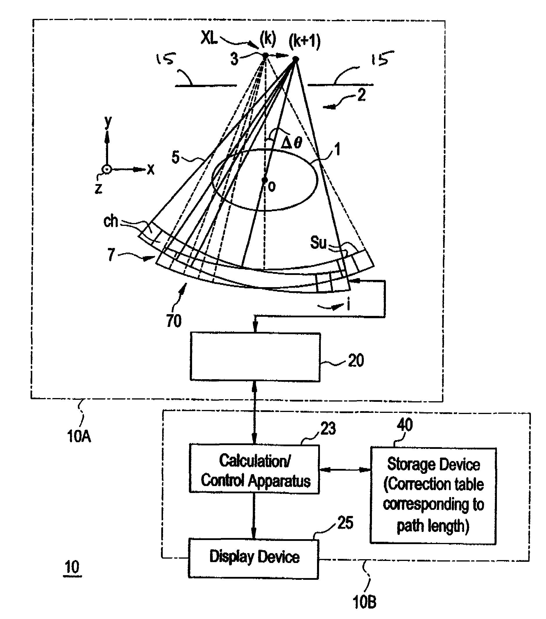
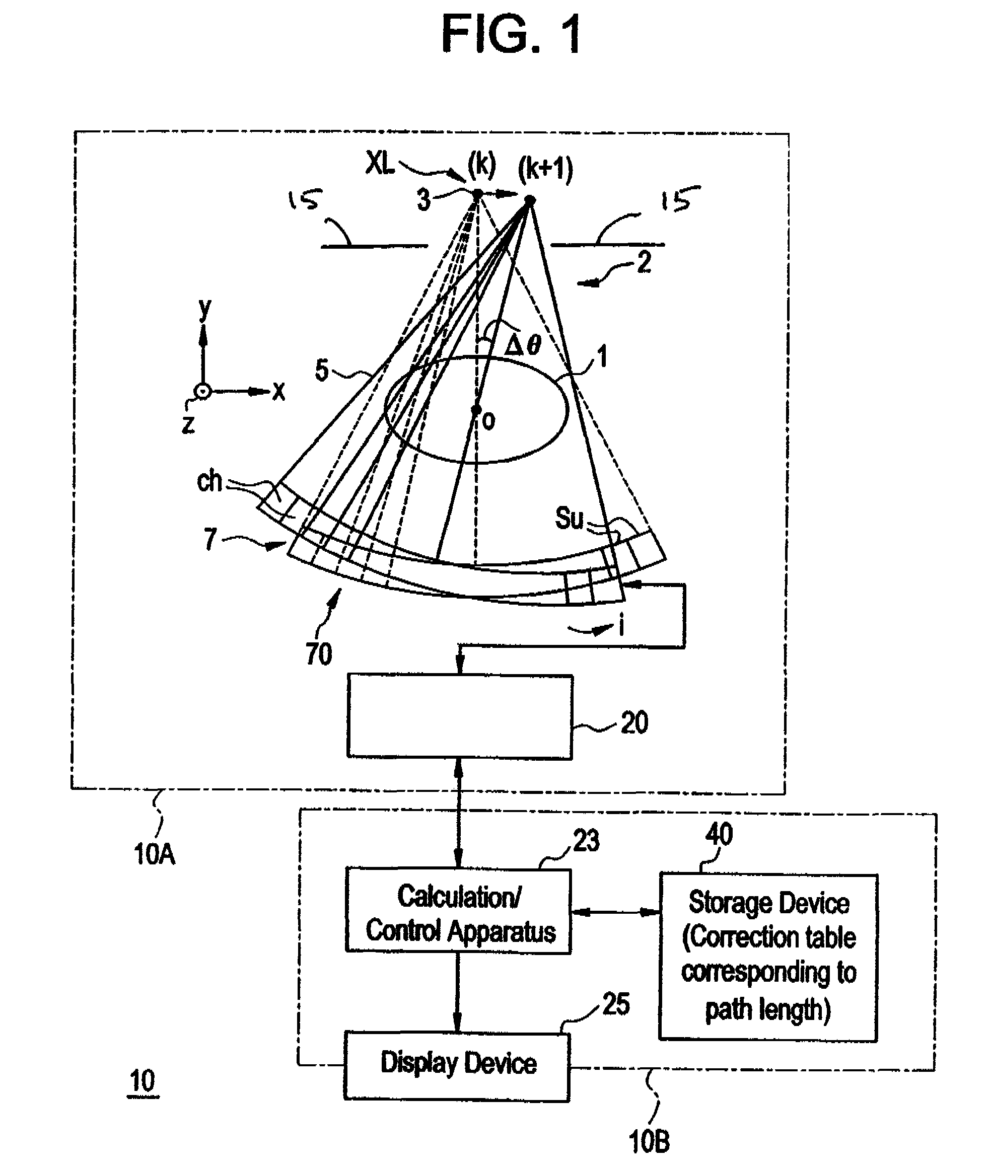
[0034]FIG. 1 is a diagram showing a general configuration of an X-ray CT apparatus in accordance with an embodiment of the present invention. The X-ray CT apparatus 10 shown in FIG. 1 comprises an X-ray CT apparatus main body 10A and a console 10B. One embodiment of the radiation computed tomography apparatus in accordance with the present invention is the X-ray CT apparatus 10 shown in FIG. 1.

[0035]The X-ray CT apparatus main body 10A comprises a rotating section 2 and a data acquisition system (DAS) 20, as shown in FIG. 1.

[0036]The rotating section 2 comprises an X-ray source XL for emitting X-rays, and an X-ray detector 70 for detecting the X-rays emitted by the X-ray source XL.

[0037]The X-r...


PUM

PropertyMeasurementUnit
widthaaaaaaaaaa
widthaaaaaaaaaa
diametersaaaaaaaaaa

Abstract

A radiation computed tomography apparatus that includes a radiation detector having a plurality of radiation detector elements arranged in a two-dimensional manner for detecting radiation passing through a subject, and a reconstructing device for arithmetically reconstructing tomographic image data for a tomographic image of the subject based on projection data for the subject from each of the plurality of radiation detector elements, the projection data obtained from values detected by the plurality of radiation detector elements, wherein the reconstructing device corrects the projection data for each of the radiation detector elements using a corrective value that is correlated with a path length of the radiation through the subject calculated from the projection data, and generates the tomographic image data based on the corrected projection data.

Description

CROSS REFERENCE TO RELATED APPLICATIONS[0001]This application claims the benefit of Japanese Application No. 2003-327412 filed Sep. 19, 2003.BACKGROUND OF THE INVENTION[0002]The present invention relates to a radiation computed tomography apparatus capable of acquiring volume data, such as a VCT (volume CT (computed tomography)) apparatus or a multi-row CT apparatus, and a tomographic image data generating method in the radiation computed tomography apparatus.[0003]Particularly, the present invention relates to a radiation computed tomography apparatus and tomographic image data generating method for reducing the influence by scatter rays through correction.[0004]Known X-ray CT apparatuses include, for example, one that acquires projection data for a subject by an X-ray detector having a plurality of X-ray detector elements arranged in a two-dimensional manner. The plurality of X-ray detector elements are positioned to have their width in a direction along a predefined axis with res...

Claims


Application Information

Patent Timeline
Patent Type & Authority Patents(United States)
IPC IPC(8): G21K1/10G01D18/00G21K1/04A61B6/00A61B6/03G01N23/04G06T11/00
CPCA61B6/032A61B6/4085A61B6/5282G01N23/046G06T11/005A61B6/583G01N2223/419A61B6/03
Inventor NUKUI, MASATAKE
Owner GE MEDICAL SYST GLOBAL TECH CO LLC
Learn More