Adapter panel, electronic equipment, and cable connector identification system

a technology of adapter panels and identification systems, applied in the direction of coupling device connections, instruments, optical elements, etc., can solve the problems of inaccuracy of measurement, electrical equipment where a plurality of plugs are inserted or removed such as a telephone switching device is subject to insertion errors, and low yield

Inactive Publication Date: 2008-05-20
HITACHT MAXELL LTD
View PDF4 Cites 94 Cited by
  • Summary
  • Abstract
  • Description
  • Claims
  • Application Information

AI Technical Summary

Benefits of technology

[0016]In view of the foregoing, it is an object of the present invention to provide a low-cost adapter panel, electronic equipment, and cable connector identification system.
[0017]To these ends, according to one aspect of the present invention, there is provided an adapter panel having an adapter where a connector including a wireless IC tag in a side surface is inserted or removed. The adapter panel includes a booster antenna placed in a position facing the wireless IC tag of the adapter when the connector is inserted to the adapter, and an equipment antenna placed in a surface of the adapter panel which is a reverse side of the surface where the connector is inserted or removed in a position corresponding to the booster antenna. This configuration allows placing the equipment antenna in a desired position, thereby providing a low-cost adapter panel.

Problems solved by technology

If such a conventional oscilloscope measures the waveform with a relatively high frequency wave, the measurement waveform fluctuates due to fluctuation in the impedance of a probe, which may result in inaccurate measurement.
Further, the electrical equipment where a plurality of plugs are inserted or removed such as a telephone switching device is subject to insertion mistake.
The printed circuit board with such a special shape is difficult to form and causes low yield.
As described above, a conventional adapter panel is not easy to manufacture and assemble, which results in high manufacturing costs.

Method used


Image

  • Adapter panel, electronic equipment, and cable connector identification system
  • Adapter panel, electronic equipment, and cable connector identification system
  • Adapter panel, electronic equipment, and cable connector identification system

Examples


first embodiment

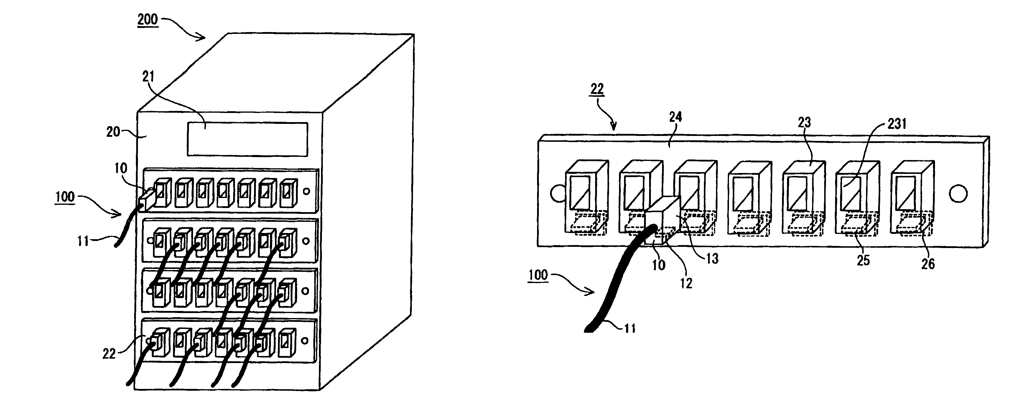
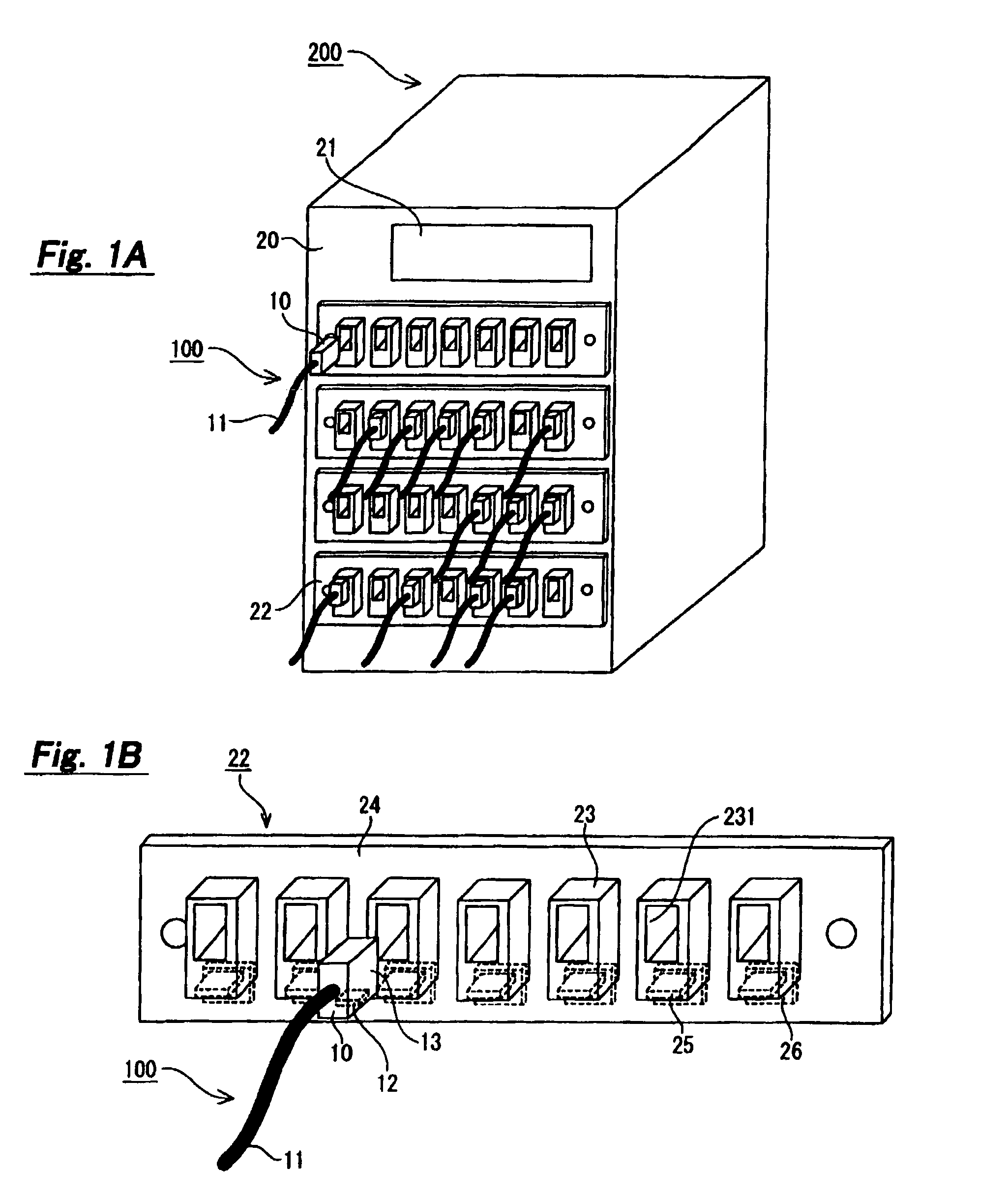
[0044]A first embodiment of the invention applies a cable connector identification system to a circuit switching device, which is also referred to hereinafter as a telephone switching device. The circuit switching device is unique in the specific structure. FIG. 1A illustrates the entire configuration of the cable connector identification system. The cable connector identification system is composed of an optical fiber cable 100 and a circuit switching device 200.

[0045]The optical fiber cable 100 has an optical fiber connector 10 and an optical fiber code 11. The optical fiber cable 100, the optical fiber connector 10, and the optical fiber code 11 are abbreviated hereinafter as the optical cable 100, the optical connector 10, and the optical code 11, respectively.

[0046]The optical connector 10 is a male plug made of insulating material such as plastic, synthetic resin, and rubber. The optical code 11 has an optical fiber inside, though not shown. The other end of the optical code 1...

second embodiment

[0072]A second embodiment of the invention applies the cable connector identification system to a telephone switching device, just like the first embodiment. FIG. 6 is a perspective view of a telephone switching device. The telephone switching device can be used by connecting an optical cable to the telephone switching device as in the first embodiment.

[0073]As shown in FIG. 6, one side surface of the telephone switching device 400 has a display section 41 and a plurality of adapter panels 42. A plurality of adapters 43 and booster antennas 44 are placed in each adapter panel 42. Further, a plurality of R / W antennas 45 are placed in the internal surface of the telephone switching device 400 where the adapter panels 42 are mounted.

[0074]A connector of a cable for telephone line connection, not shown, is inserted to each adapter 43 in the same way as the optical connector 10 and they are electrically connected inside the adapter 43. Further, the Coil-on-Chip RFID 12 is placed in the c...

third embodiment

[0080]A third embodiment of the invention applies the cable connector identification system to a telephone switching device, just like the second embodiment. The configuration of the telephone switching device is the same as described in FIG. 6. The telephone switching device 400 of the third embodiment is unique in the internal processing just like the second embodiment.

[0081]The cable connector identification system of the third embodiment is used by connecting the optical cable 100 to the telephone switching device 400 as in the first embodiment. In the optical cable 100 connected to the switching device 400, the core alignment accuracy to align the optical axis is so important as to greatly affect the communication performance. However, it is inevitable that the core alignment accuracy deteriorates by repeating the insertion and removal of the optical cable 100 into and from the telephone switching device 400. Thus, it is necessary to replace the optical cable 100 every after 50...


PUM


Abstract

An adapter panel has an adapter where a connector including a wireless IC tag in a side surface is inserted or removed. The adapter panel includes a booster antenna placed in a position facing the wireless IC tag of the adapter when the connector is inserted to the adapter, and an equipment antenna placed in a surface of the adapter panel which is a reverse side of the surface where the connector is inserted or removed in a position corresponding to the booster antenna. The adapter panel is applicable to electronic equipment and a cable connector identification system.

Description

BACKGROUND OF THE INVENTION[0001]1. Field of the Invention[0002]The present invention relates to adapter panels, electronic equipment, and cable connector identification systems, and particularly to an adapter panel where a cable with a connector having an IC device is inserted and removed, electronic equipment having the adapter panel, and a cable connector identification system identifying the connector of the cable.[0003]2. Description of Related Art[0004]Various electrical equipment input or output information by a cable. For example, an oscilloscope has a connector jack to connect a removable cable integral with a connector, thereby inputting waveform information.[0005]If such a conventional oscilloscope measures the waveform with a relatively high frequency wave, the measurement waveform fluctuates due to fluctuation in the impedance of a probe, which may result in inaccurate measurement. Further, the electrical equipment where a plurality of plugs are inserted or removed such...

Claims


Application Information

Patent Timeline
Patent Type & Authority Patents(United States)
IPC IPC(8): G06K19/06G06K7/08G02B6/00H01R9/24H01R13/46H01R13/64H01R13/648H01R13/703H01R29/00
CPCG06K7/10178G06K7/10336H01R9/2475H01R13/465H01R13/64H01R13/7038H01R29/00H01R2201/02G02B6/3825G02B6/3895G02B6/3897
Inventor KANEKO, TOSHIYUKI
Owner HITACHT MAXELL LTD
Why Eureka
Try Eureka