Scan method and topology for capacitive sensing

a capacitive sensing and topology technology, applied in the direction of resistance/reactance/impedence, instruments, measurement devices, etc., can solve the problems of increasing the circuit components of the resulting system, and the need for an extra inpu

Inactive Publication Date: 2008-05-20
MONTEREY RES LLC
View PDF27 Cites 96 Cited by
  • Summary
  • Abstract
  • Description
  • Claims
  • Application Information

AI Technical Summary

Benefits of technology

[0024]In this way, an input event at one or more of the N capacitive sensors can result in the sensors continuing to be scanned.

Problems solved by technology

A drawback to an arrangement like that of FIG. 9 can be the increase in circuit components of the resulting system, as well as the need for an extra input to accommodate the second capacitor.

Method used


Image

  • Scan method and topology for capacitive sensing
  • Scan method and topology for capacitive sensing
  • Scan method and topology for capacitive sensing

Examples


embodiment example

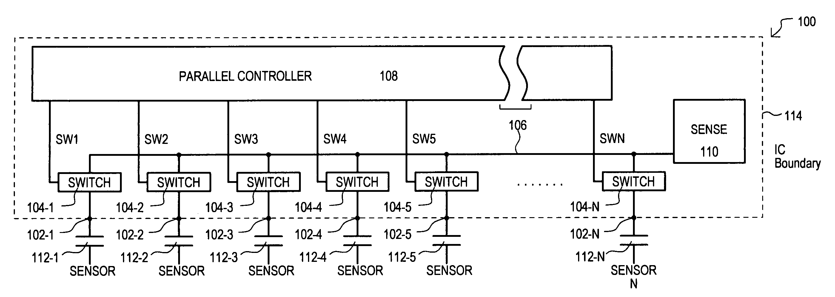
[0099]The embodiment example assumes the same general system values as the preceding conventional case. However, it will be assumed that two capacitive sensors are grouped together. Accordingly, in such an arrangement, a background count (no load) can be 250 counts, while a loaded count can be 246 counts.

[0100]Within the system, noise resulting from quantization remains at 0.3 rms. However, the comparator adds 0.25 rms, as the steps for counting are larger. This can yields an rms noise value of 0.4.

[0101]A calculation of the SNR in dB is given as:

20 log10(4 count signal / 0.4 count noise)=20.0 dB.

From the above, sensing based on combining two capacitive sensors results in a loss of 8.5 dB, which is less than a full factor of four. This loss in SNR is believed to be outweighed by the 4× increase in scan speed for an array of capacitive sensors, and corresponding reduction in power consumption.

[0102]It is understood that the embodiments of the invention may be practiced in the absence o...


PUM


Abstract

A capacitive sensing system (100) can connect groups of capacitive sensors (112-1 to 112-N) to a common node (106) to detect change in capacitance. States of a set of capacitive sensors (112-1 to 112-N) can thus be scanned faster than approaches that scan such sensors one-by-one. Faster scanning can allow for reduced power consumption in applications that only periodically scan the set of capacitive sensors (112-1 to 112-N).

Description

TECHNICAL FIELD[0001]The present invention relates generally to devices employing capacitive sensing, and more particularly to methods and topologies that scan multiple capacitive sensors.BACKGROUND OF THE INVENTION[0002]Capacitive sensors can provide a change in capacitance that represents the proximity of a sensed object. As but one very particular example, capacitive sensors can detect the presence of a pointing object, such as a finger, stylus, or pen. In such an application, an array of capacitive sensors can be scanned, and thereby serve as a pointing device in an electronic system (e.g., portable music player, personal digital assistant, tablet personal computer (PC), notebook PC, desktop PC, to name but a few). Capacitive sensors can be more robust and / or compact than other types of sensors that may include moving parts or more complex position detection approaches.[0003]As understood from above, capacitive sensors can be used in portable devices, such as those operating off...

Claims


Application Information

Patent Timeline
Patent Type & Authority Patents(United States)
IPC IPC(8): G01R27/26
CPCG01D5/24
Inventor KUTZ, HAROLDSNYDER, WARRENWILLIAMS, TIMPAGE, ANDREW
Owner MONTEREY RES LLC
Why Eureka
Try Eureka