Magnetic head for perpendicular magnetic recording and method of manufacturing same

a perpendicular magnetic and recording technology, applied in the direction of head winding construction, data recording, instruments, etc., can solve the problems of difficult to precisely form the pole layer having such a shape, difficult to control the level at which polishing is stopped with precision, and difficult to precisely form the pole layer through the foregoing method

Active Publication Date: 2008-05-20
HEADWAY TECH INC
View PDF28 Cites 40 Cited by
  • Summary
  • Abstract
  • Description
  • Claims
  • Application Information

AI Technical Summary

Benefits of technology

[0027]It is an object of the invention to provide a magnetic head for perpendicular magnetic recording that is capable of preventing problems resulting from the skew and capable of precisely forming a pole layer capable of introducing a magnetic flux of great magnitude to the medium facing surface, and to provide a method of manufacturing such a magnetic head.
[0049]According to the magnetic head for perpendicular magnetic recording of the invention or the method of manufacturing the magnetic head for perpendicular magnetic recording of the invention, the pole layer incorporates the first and second portions, and the surface of the first portion closer to the substrate is located farther from the substrate than the surface of the second portion closer to the substrate. According to the invention, it is possible to form the encasing groove in advance and to form the pole layer such that at least part of the pole layer is placed in the encasing groove. As a result, according to the invention, it is possible to prevent problems resulting from the skew and to form the pole layer with precision that is capable of introducing a magnetic flux of great magnitude to the medium facing surface.
[0050]In the invention, the first portion may include a portion having a width equal to the track width and having a width that does not change in accordance with the distance from the medium facing surface, and a greatest width of the second portion may be greater than the track width. In this case, it is possible to effectively introduce a magnetic flux of great magnitude to the medium facing surface through the pole layer while reducing the thickness of the pole layer taken in the medium facing surface.
[0051]In the invention, the surface of the first portion closer to the substrate may be parallel to the surface of the first portion farther from the substrate. In this case, it is possible to prevent variations in thickness of the pole layer in the medium facing surface.
[0052]In the invention, the surface of the first portion farther from the substrate may be located closer to the substrate than the surface of the second portion farther from the substrate. In this case, it is possible to more effectively introduce a magnetic flux of great magnitude to the medium facing surface through the pole layer while reducing the thickness of the pole layer taken in the medium facing surface.

Problems solved by technology

In a magnetic disk drive of the perpendicular magnetic recording system that exhibits a better capability of writing on a recording medium than the longitudinal magnetic recording system, in particular, if the above-mentioned skew is created, problems arise, such as a phenomenon in which data stored on an adjacent track is erased when data is written on a specific track (that is hereinafter called adjacent track erasing) or unwanted writing is performed between adjacent two tracks.
It is difficult through the foregoing method of forming the pole layer to control the level at which polishing is stopped with precision.
Therefore, the foregoing method of forming the pole layer has a problem that it is difficult to control the track width with precision.
However, it is difficult to precisely form the pole layer having such a shape that the portion near the medium facing surface has a thickness smaller than that of the other portion.
In this case, however, there arises a problem that it is difficult to align the main pole layer and the yoke layer with accuracy and the writing characteristic varies if the main pole layer and the yoke layer are misaligned.
In this portion in which the thickness varies, it is likely that flux leakage from the pole layer occurs.
Consequently, if the portion is close to the medium facing surface, the leakage flux from the portion reaches the medium facing surface and further leaks to the outside from the medium facing surface.
As a result, the effective track width is increased and / or the above-mentioned problems resulting from the skew occur.
As a result, the effective track width increases and / or the above-mentioned problems resulting from the skew occur.
However, it is difficult to control the level at which the polishing is stopped with precision in this method as described above, and it is therefore difficult to control the track width with precision.

Method used


Image

  • Magnetic head for perpendicular magnetic recording and method of manufacturing same
  • Magnetic head for perpendicular magnetic recording and method of manufacturing same
  • Magnetic head for perpendicular magnetic recording and method of manufacturing same

Examples


first embodiment

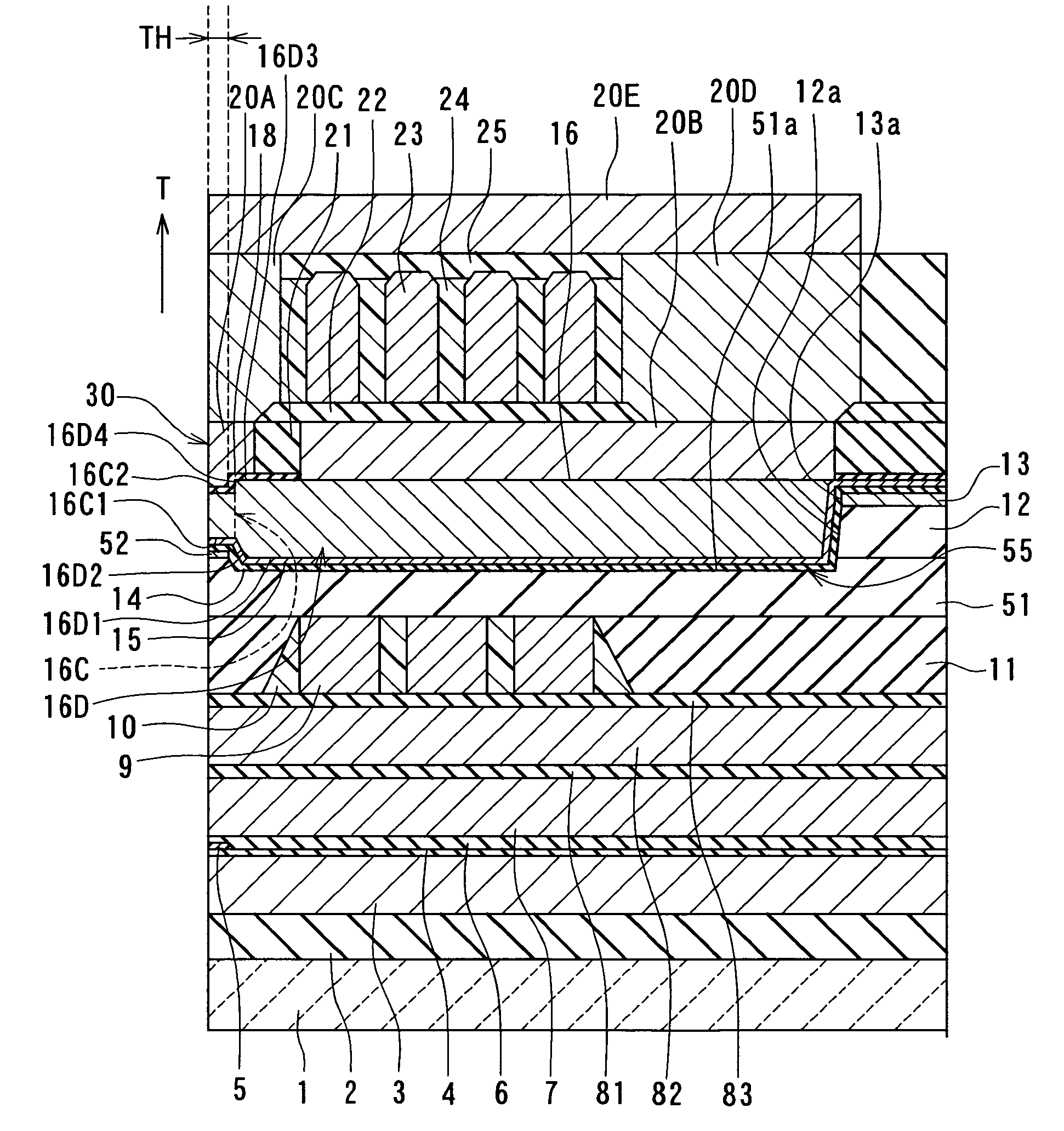
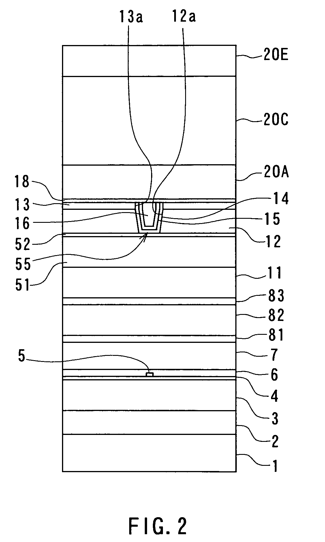
[0098]Preferred embodiments of the invention will now be described in detail with reference to the accompanying drawings. Reference is now made to FIG. 2 and FIG. 3 to describe the configuration of a magnetic head for perpendicular magnetic recording of a first embodiment of the invention. FIG. 2 is a front view for illustrating the medium facing surface of the magnetic head of the embodiment. FIG. 3 is a cross-sectional view for illustrating the configuration of the magnetic head of the embodiment. FIG. 3 illustrates a cross section orthogonal to the medium facing surface and a surface of a substrate. The arrow indicated with T in FIG. 3 shows the direction of travel of a recording medium.

[0099]As shown in FIG. 2 and FIG. 3, the magnetic head for perpendicular magnetic recording (hereinafter simply called the magnetic head) of the embodiment comprises: a substrate 1 made of a ceramic such as aluminum oxide and titanium carbide (Al2O3—TiC); an insulating layer 2 made of an insulatin...

modification examples

[0179]First to fourth modification examples of the embodiment will now be described. FIG. 17 is a cross-sectional view illustrating a portion of the pole layer 16 near the medium facing surface 30 and a portion around this portion of a magnetic head of the first modification example. In the first modification example, the second front end face 16D4 of the pole layer 16 is tilted with respect to the direction orthogonal to the top surface of the substrate 1 such that the thickness of the pole layer 16 gradually increases as the distance from the medium facing surface 30 increases in the region in which the front end face 16D4 is located. The second front end face 16D4 preferably forms an angle that is equal to or greater than 30 degrees and smaller than 80 degrees with respect to the top surface of the substrate 1. In the first modification example, when a portion of the magnetic layer 16P is etched by ion beam etching to form the surfaces 16C2 and 16D4, the direction in which ion be...

second embodiment

[0186]A magnetic head and a method of manufacturing the same of a second embodiment of the invention will now be described. Reference is now made to FIG. 21A to FIG. 29A and FIG. 21B to FIG. 29B to describe the method of manufacturing the magnetic head of the second embodiment. FIG. 21A to FIG. 29A each illustrate a cross section of a layered structure obtained in the course of manufacturing process of the magnetic head, the cross section being orthogonal to the medium facing surface and the substrate. FIG. 21B to FIG. 29B each illustrate a cross section of a portion of the layered structure near the medium facing surface, the cross section being parallel to the medium facing surface. In FIG. 21A to FIG. 29A and FIG. 21B to FIG. 29B, portions located higher than the coil 9 and the insulating layers 10 and 11 are only shown.

[0187]The method of manufacturing the magnetic head of the second embodiment includes the steps up to the step of flattening the top surfaces of the coil 9 and th...


PUM

PropertyMeasurementUnit
thicknessaaaaaaaaaa
specific distanceaaaaaaaaaa
thicknessaaaaaaaaaa

Abstract

A pole layer incorporates: a first portion having an end face located in a medium facing surface; and a second portion having a thickness greater than that of the first portion. A surface of the first portion closer to a substrate is located farther from the substrate than a surface of the second portion closer to the substrate. A surface of the first portion farther from the substrate is located closer to the substrate than a surface of the second portion farther from the substrate. At least a portion of the pole layer is placed in an encasing groove formed in a region extending from a first encasing layer through a second encasing layer to a nonmagnetic metal layer.

Description

BACKGROUND OF THE INVENTION[0001]1. Field of the Invention[0002]The present invention relates to a magnetic head for perpendicular magnetic recording that is used for writing data on a recording medium by using a perpendicular magnetic recording system and to a method of manufacturing such a magnetic head.[0003]2. Description of the Related Art[0004]The recording systems of magnetic read / write devices include a longitudinal magnetic recording system wherein signals are magnetized in the direction along the surface of the recording medium (the longitudinal direction) and a perpendicular magnetic recording system wherein signals are magnetized in the direction orthogonal to the surface of the recording medium. It is known that the perpendicular magnetic recording system is harder to be affected by thermal fluctuation of the recording medium and capable of implementing higher linear recording density, compared with the longitudinal magnetic recording system.[0005]Like magnetic heads fo...

Claims


Application Information

Patent Timeline
Patent Type & Authority Patents(United States)
IPC IPC(8): G11B5/147
CPCG11B5/1278G11B5/3116G11B5/3163G11B5/3169
Inventor SASAKI, YOSHITAKAITOH, HIROYUKIARAKI, HIRONORITANEMURA, SHIGEKIISHIZAKI, KAZUO
Owner HEADWAY TECH INC
Why Eureka
Try Eureka