Power factor correction circuit

a power factor and circuit technology, applied in the direction of electric variable regulation, process and machine control, instruments, etc., can solve the problems of product failure in safe regulations, increased pwm unit cost, and high consumption of sensing resistors in conventional pfc circuits, so as to reduce consumption and improve operation efficiency

Inactive Publication Date: 2008-05-20
SPI ELECTRONICS
View PDF4 Cites 12 Cited by
  • Summary
  • Abstract
  • Description
  • Claims
  • Application Information

AI Technical Summary

Benefits of technology

[0003]In view of the problems described above, the object of the present invention is to provide a circuit whose power factor can be corrected for reducing the consumption so as to conform to the safe regulations and improve the operation efficiency.
[0004]The present invention provides a power factor correction (PFC) circuit. The PFC circuit includes an energy storage inductor, an output diode, a pulse width modulation unit, a switch unit and a converter transformer, which is formed by a primary and a secondary windings wound on a magnetic material. The PFC circuit is connected between a rectifier unit and a main transformer at the front end of a power output unit, so that the DC current outputted by the rectifier unit can pass through the converter transformer of the PFC circuit for producing an induced current, which is reduced in proportion to the DC current passing through the primary winding, at the secondary winding. Furthermore, a sensing resistor is disposed to cross the secondary winding for obtaining a reference voltage, and the reference voltage is supplied to the PWM unit for producing the duty cycle of the switch unit, so that the switch unit can regulate the phase of the DC current to be close to the phase of the DC voltage.

Problems solved by technology

However, since the output power of the power supply is gradually increased and also the outputted DC current, the consumption of the sensing resistor 5 in the conventional PFC circuit will become higher, too.
However, this may increase the cost of the PWM unit.
But, this method causes the consumption of the PFC circuit which nevertheless causes the product fail in safe regulations.

Method used


Image

  • Power factor correction circuit
  • Power factor correction circuit
  • Power factor correction circuit

Examples


Embodiment Construction

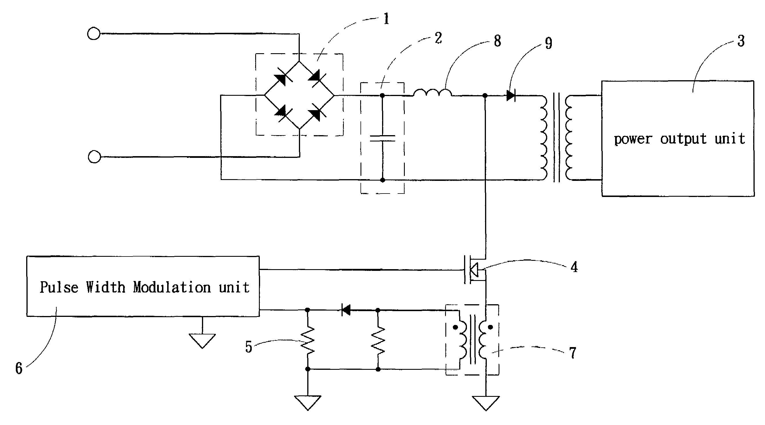
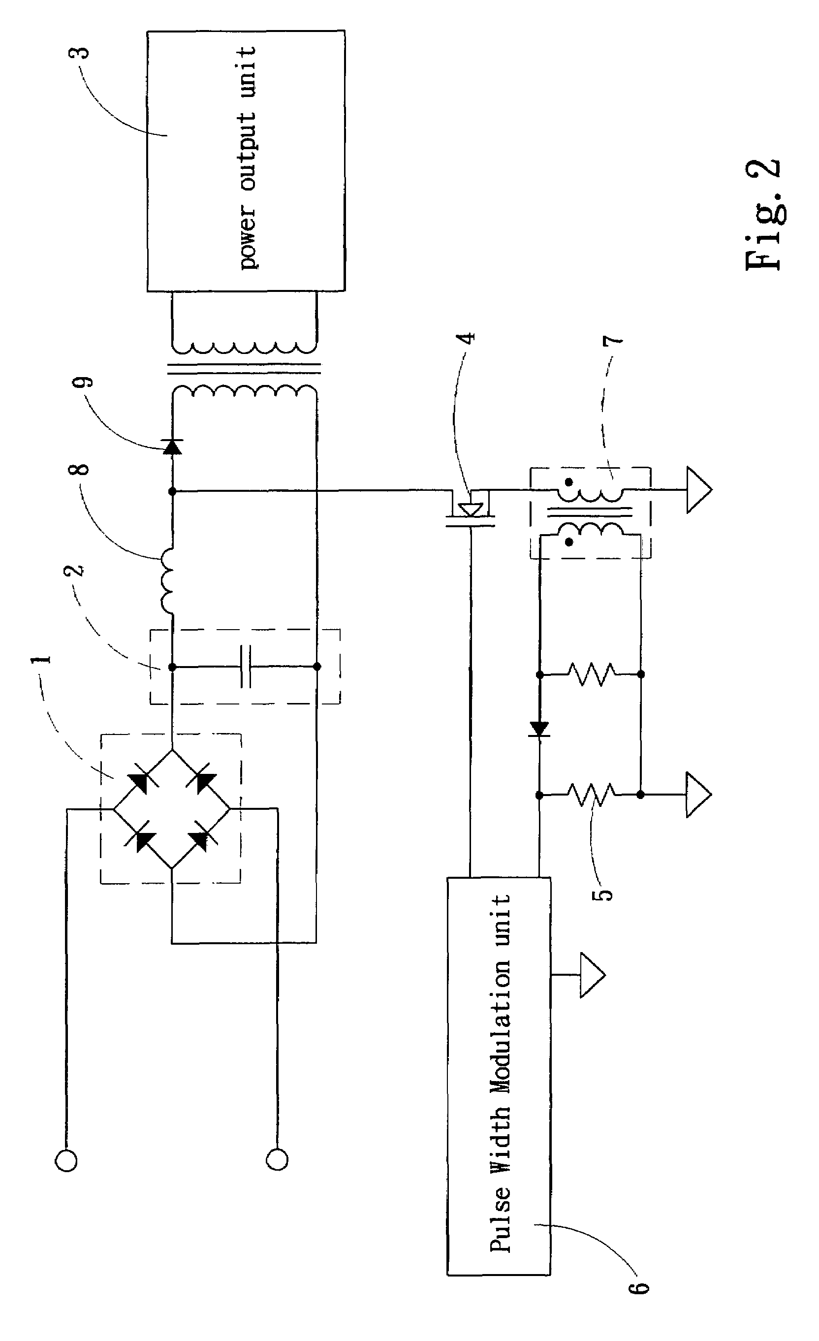
[0008]Please refer to FIG. 2 which shows a preferred embodiment according to the present invention. The present invention is applied to the PFC (Power Factor Correction) circuit in a power supplier. The PFC circuit is connected between a rectifier unit 1 and a main transformer at the front end of a power output unit 3. The power supplier has a rectifier unit 1 for transforming an AC power into a DC power and a power output unit 3 for outputting DC power, and further, between the rectifier unit 1 and the power output unit 3, a filter unit 2 is positioned. As to the PFC circuit according to the present invention, it is parallel connected between the rectifier unit 1 and the power output unit 3. The PFC circuit includes an energy storage inductor 8, an output diode 9, a switch unit 4, a PWM (Pulse Width Modulation) unit 6, a sensing resistor 5 and a converter transformer 7, which is formed by winding a primary and a secondary windings on a magnetic material, wherein the DC current outp...


PUM


Abstract

A power factor correction circuit used for regulating the phase of a DC current outputted from a rectifier unit in a power supply includes an energy inductor, an output diode, a switch unit, a pulse width modulation unit, a sensing resistor, and a converter transformer. The converter transformer utilizes the DC current outputted from the rectifier unit to generate an induced current, which will pass through the two ends of the sensing resistor to produce a reference voltage, thereby the pulse width modulation unit can produce the duty cycle for the switch unit according to the reference voltage, so that the switch unit can regulate the phase of the DC current through controlling the flowing direction of the DC current.

Description

FIELD OF THE INVENTION[0001]The present invention is related to a PFC (Power Factor Correction) circuit which utilizes a transformer and a resistor to acquire the reference voltage required by a PWM (Pulse Width Modulation) unit so as to reduce the power consumption.BACKGROUND OF THE INVENTION[0002]Nowadays, power suppliers have been commonly applied to various electronic products, and owing to the developed technology, the output power thereof is gradually increased. However, for further raising the power, it has to increase the operation efficiency. Generally, the efficiency of power supply is referenced to a power factor, which represents the relationship between the effective power and sum power consumption (apparent power), that is, the rate of effective power to sum power consumption, so that the closer the effective power to the sum power consumption, the higher the power factor, namely, the better the operation efficiency. Therefore, the improvement of operation efficiency c...

Claims


Application Information

Patent Timeline
Patent Type & Authority Patents(United States)
IPC IPC(8): H02M3/24
CPCH02M1/4225Y02B70/126Y02B70/10Y02P80/10
Inventor CHENG, ALLEN
Owner SPI ELECTRONICS
Why Eureka
Try Eureka