Nonresonant micromachined gyroscopes with structural mode-decoupling

a micro-machined gyroscope and non-resonant technology, applied in the direction of acceleration measurement using interia force, turn-sensitive devices, instruments, etc., can solve the problems of damping change, reduced sensitivity to structural and thermal parameter fluctuations, increased bandwidth, etc., to minimize instability and large oscillation amplitude

Active Publication Date: 2008-05-27
RGT UNIV OF CALIFORNIA
View PDF6 Cites 48 Cited by
  • Summary
  • Abstract
  • Description
  • Claims
  • Application Information

AI Technical Summary

Benefits of technology

[0007]In the illustrated embodiment of the invention, we propose a micromachined gyroscope system utilizing dynamical amplification to achieve large oscillation amplitudes without resonance, while mechanically decoupling the drive direction oscillations from the sense direction oscillations. The overall dynamical system is comprised of three proof masses. The sense-direction oscillator is made up of the second and third masses, designed to amplify response in the sense-mode. The first mass and the combination of the second and third masses form the drive-direction oscillator. The drive and sense-mode oscillators are mechanically decoupled, minimizing instability due to dynamical coupling between the drive and sense modes. The frequency response of both of the drive and sense-mode oscillators have two resonant peaks and a flat region between the peaks. By designing the drive and sense antiresonance frequencies to match, the flat-region frequency band of the oscillators are overlapped, defining the nominal operation region of the device, where the response gain is less sensitive to parameter variations.
[0008]Utilizing dynamical amplification in the sense and drive mode oscillators instead of resonance, increased bandwidth and reduced sensitivity to structural and thermal parameter fluctuations and damping changes are achieved. The improved robustness and long-term stability over the operating time of the device is expected to relax control system requirements and tight fabrication and packaging tolerances.
[0010]The drive-mode oscillator and sense-mode oscillator utilize dynamical amplification in the drive and sense directions to achieve large oscillation amplitudes without resonance resulting in increased bandwidth and reduced sensitivity to structural and thermal parameter fluctuations and damping changes.
[0011]One of the three masses is an intermediate proof mass and another is a sensing element. The drive-mode oscillator and sense-mode oscillator are mechanically decoupled in the drive direction from the sense direction for robustness and long-term stability. The Coriolis force that excites the sensing element is generated by the intermediate proof mass with a larger mass, resulting in larger Coriolis forces for increased sensor sensitivity so that control system requirements and tight fabrication and packaging tolerances are relaxed, mode-matching is eliminated, and instability and zero-rate drift due to mechanical coupling between the drive and sense modes is minimized.
[0020]The third mass acts as the vibration absorber in the sense-mode oscillator to achieve large sense direction oscillation amplitudes due to mechanical amplification.

Problems solved by technology

The drive-mode oscillator and sense-mode oscillator utilize dynamical amplification in the drive and sense directions to achieve large oscillation amplitudes without resonance resulting in increased bandwidth and reduced sensitivity to structural and thermal parameter fluctuations and damping changes.

Method used


Image

  • Nonresonant micromachined gyroscopes with structural mode-decoupling
  • Nonresonant micromachined gyroscopes with structural mode-decoupling
  • Nonresonant micromachined gyroscopes with structural mode-decoupling

Examples


Embodiment Construction

[0039]First, we present a detailed analysis of the conventional gyroscope dynamics emphasizing the related challenges. Second, the design approach and the principle of operation are presented, together with a detailed comparison of the system characteristics to a conventional gyroscope. Third, the dynamics of the device is then analyzed, and fourth, a MEMS implementation of the design concept is presented along with an approach for determining optimal system parameters to maximize sensor performance.

[0040]Detailed Analysis Of The Conventional Gyroscope Dynamics

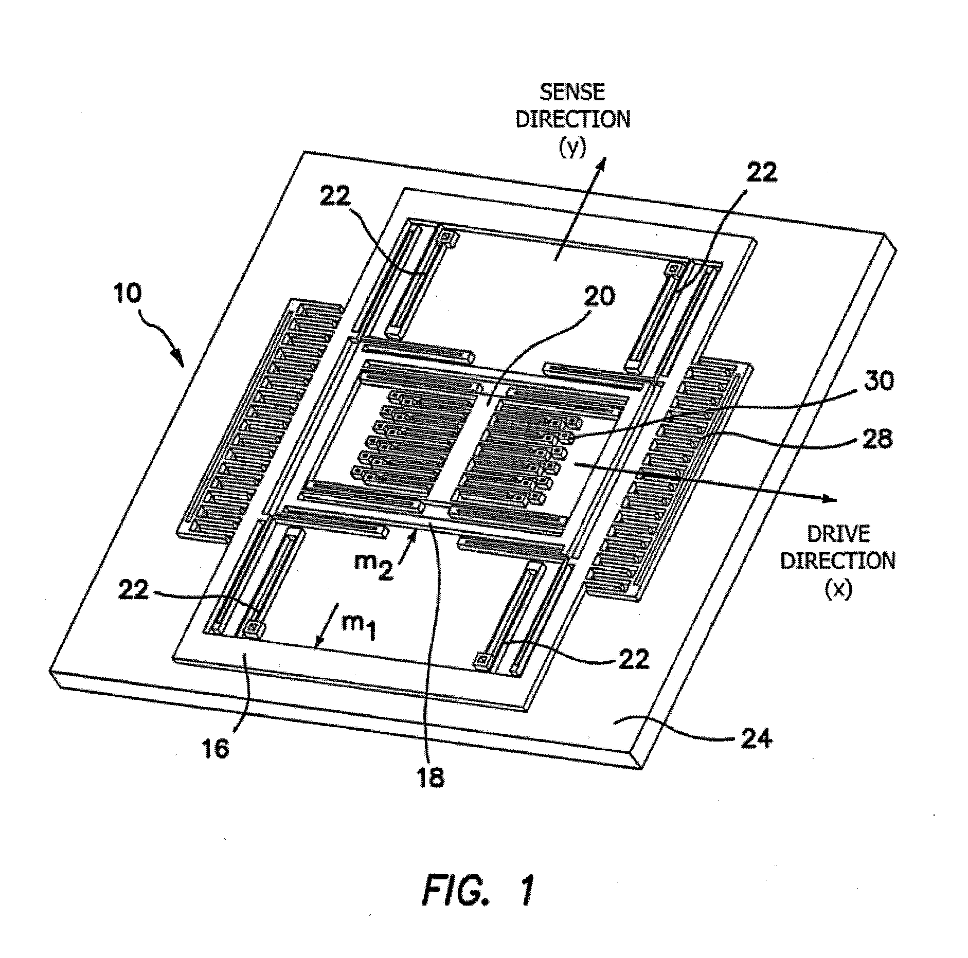
[0041]Almost all existing micromachined rate gyroscopes operate on the principle of rotation-induced Coriolis acceleration detection using a single vibrating proof mass suspended above the substrate. The proof mass is supported by anchored flexures, which serve as the flexible suspension between the proof mass and the substrate, making the mass free to oscillate in two orthogonal directions: the drive direction (-axis) and the...


PUM


Abstract

A four-degrees-of-freedom (DOF) nonresonant micromachined gyroscope utilizes a dynamical amplification both in the drive-direction oscillator and the sense-direction oscillator, which are structurally decoupled, to achieve large oscillation amplitudes without resonance. The overall dynamical system is comprised of three proof masses. The second and third masses form the sense-direction oscillator. The first mass and the combination of the second and third masses form the drive-direction oscillator. The frequency responses of the drive and sense-mode oscillators have two resonant peaks and a flat region between the peaks. The device is nominally operated in the flat regions of the response curves belonging to the drive and sense-mode oscillators, where the gain is less sensitive to frequency fluctuations. This is achieved by designing the drive and sense anti-resonance frequencies to match.

Description

BACKGROUND OF THE INVENTION[0001]1. Field of the Invention[0002]The invention relates to micromachined gyroscopes and in particular to four-degrees-of-freedom (DOF) nonresonant micromachined gyroscopes having three proof masses.[0003]2. Description of the Prior Art[0004]Micromachined gyroscopes are projected to become a potential alternative to expensive and bulky conventional inertial sensors. With micromachining processes allowing mass-production of micromechanical systems on a chip together with their control and signal conditioning electronics, low-cost and microsized gyroscopes provide high accuracy rotation measurements leading to an even broader application spectrum, ranging from advanced automotive safety systems and on-chip navigation systems to interactive consumer electronics.[0005]However, due to unfavorable effects of scaling, the current state of the art micromachined gyroscopes require an order of magnitude improvement in performance, stability, and robustness. The co...

Claims


Application Information

Patent Timeline
Patent Type & Authority Patents(United States)
IPC IPC(8): G01P9/04G01C19/56
CPCG01C19/5719
Inventor ACAR, CENKSHKEL, ANDREI M.
Owner RGT UNIV OF CALIFORNIA
Why Eureka
Try Eureka