Vehicular brake system component

a brake system and component technology, applied in the direction of brake systems, brake components, brake cylinders, etc., can solve the problems of spoiling sealing performance, excessive expansion or contraction of the diaphragm, etc., and achieve satisfactory peeling strength, satisfactory sealing performance, and enhanced peeling strength between the metal member and the adhesive layer

Active Publication Date: 2008-05-27
NHK SPRING CO LTD +2
View PDF21 Cites 12 Cited by
  • Summary
  • Abstract
  • Description
  • Claims
  • Application Information

AI Technical Summary

Benefits of technology

[0011]The vehicular brake system component according to the first aspect of the invention comprises the sealable bonded component having the metal member and the elastic rubber member bonded to each other and located so as to touch the brake fluid. Therefore, the sealing performance of the bonded component can be secured for a prolonged time.
[0024]According to the present invention, there may be provided a vehicular brake system component that can secure its sealing performance for a long period of time.

Problems solved by technology

In the case of the accumulator of which the interior of the pressure vessel is divided into the gas and liquid chambers by the diaphragm, however, the diaphragm sometimes may excessively extend or contract when the gas is sealed into the gas chamber or if the pressure in the liquid chamber falls below a given level during use.
Thus, an undue force may possibly locally act on a seal member provided on an elastic end of the diaphragm, thereby spoiling the sealing performance.

Method used


Image

  • Vehicular brake system component
  • Vehicular brake system component
  • Vehicular brake system component

Examples


first embodiment

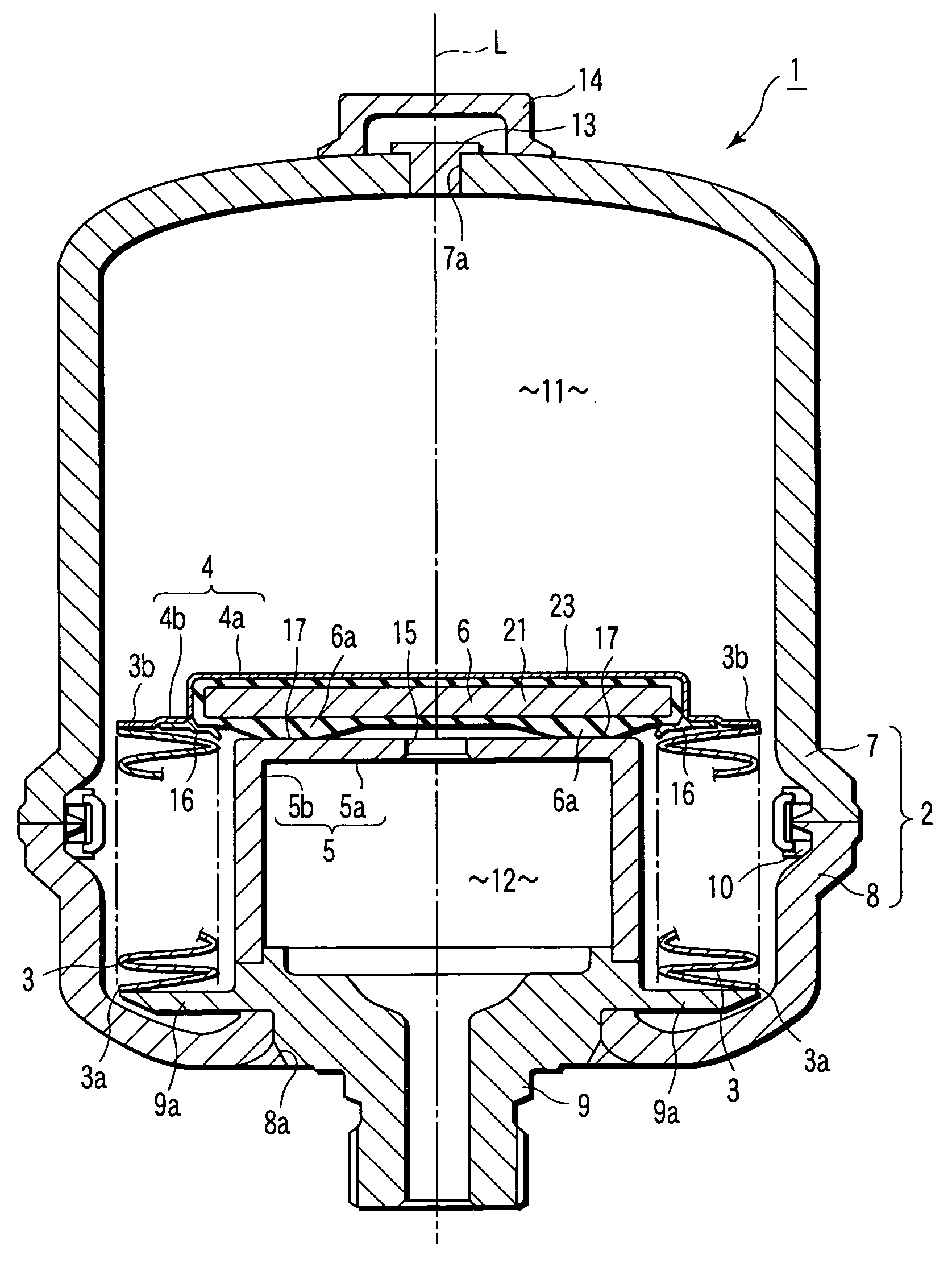
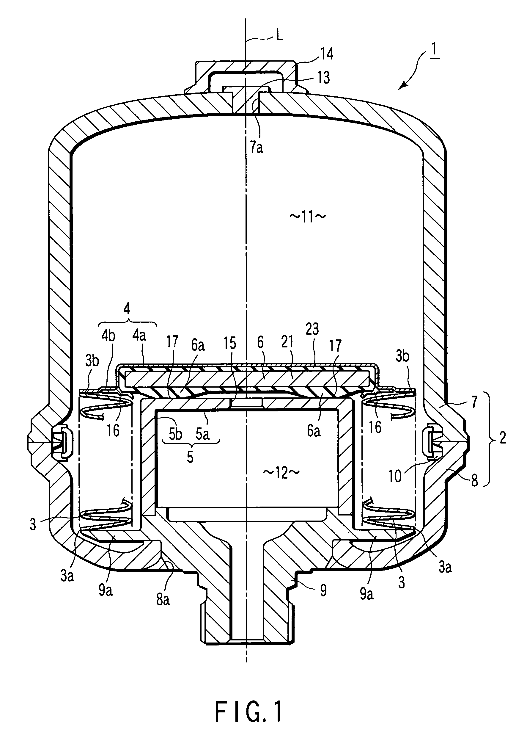
[0039]the present invention will now be described with reference to FIGS. 1 and 2. In connection with the present embodiment, an accumulator will be explained as a vehicular brake system component.

[0040]As shown in FIG. 1, an accumulator 1 as a vehicular brake system component comprises a pressure vessel 2, metallic bellows 3 as a diaphragm, cap portion 4, partition wall 5, seal member 6, etc. The seal member 6 serves also as a sealable bonded component.

[0041]The accumulator 1 is used to store pressure generated in a hydraulic-pressure device and absorb hydraulic pulsation. In the description of the present embodiment to follow, the accumulator 1 is supposed to be used as the hydraulic-pressure device in a hydraulic brake device as a vehicular brake system that is attached to a vehicle such as an automobile.

[0042]The pressure vessel 2 has first and second shells 7 and 8. Each of the first and second shells 7 and 8 is a bottomed cylinder that is formed by forging or the like. The out...

second embodiment

[0131]the present invention will now be described with reference to FIGS. 8 to 10. In connection with the present embodiment, a master cylinder will be described as an example of the vehicular brake system component. A master cylinder 31 of the present embodiment is constructed in the same manner as an existing master cylinder except for the structure of a center valve 34.

[0132]As shown in FIG. 8, the master cylinder 31 is a device that converts an operating force applied to an input mechanism through a brake pedal or the like into a liquid pressure. It comprises a body 32, a rod 33, the center valve 34 for use as a liquid pressure generating mechanism, a piston 35, etc. In the body 32, the rod 33, valve 34, and piston 35 are arranged in the order named. The rod 33 has an abutting portion 33a on the side of the valve 34. The valve 34 is a sealable bonded component that serves also as a seal member. The center valve 34 has a metal member 21, adhesive layer 22, and elastic rubber memb...

third embodiment

[0136]the present invention will now be described with reference to FIGS. 11 to 12. In connection with the present embodiment, a plunger pump will be described as an example of the vehicular brake system component. A plunger pump 41 of the present embodiment is constructed in the same manner as an existing plunger pump except for the structure of a seal member 44.

[0137]As shown in FIG. 11, the plunger pump 41 comprises a body 42, a shaft 43, the seal member 44, etc. The shaft 43 is located in the body 42. Further, a pump suction chamber 45 is defined in the body 42. In the plunger pump 41 that is used as the brake system component, the suction chamber 45 doubles as a cam chamber. The ring-shaped seal member 44 cuts off a brake fluid from the suction chamber 45. The seal member 44 is located along the outer periphery of the shaft 43. The seal member 44 is also a sealable bonded component. It has a metal member 21, adhesive layer 22, and elastic rubber member 23, and is constructed in...


PUM


Abstract

A vehicular brake system component is used in a brake system of a vehicle. The brake system component includes a sealable bonded component having a metal member and an elastic rubber member bonded to each other and located so as to touch a brake fluid.

Description

CROSS-REFERENCE TO RELATED APPLICATIONS[0001]This application is based upon and claims the benefit of priority from prior Japanese Patent Applications No. 2003-282860, filed Jul. 30, 2003; and No. 2004-145048, filed May 14, 2004, the entire contents of both of which are incorporated herein by reference.BACKGROUND OF THE INVENTION[0002]1. Field of the Invention[0003]The present invention relates to a vehicular brake system component, such as an accumulator, used in a brake system of a vehicle.[0004]2. Description of the Related Art[0005]A known vehicular brake system component, e.g., an accumulator, comprises a pressure vessel and a diaphragm. The pressure vessel has a gas chamber in which a compressed gas is sealed and a liquid chamber filled with a liquid, such as oil. The diaphragm divides the gas and liquid chambers and has one end capable of extending and contracting in the axial direction of the vessel. The diaphragm of the accumulator of this type requires elasticity to cope w...

Claims


Application Information

Patent Timeline
Patent Type & Authority Patents(United States)
IPC IPC(8): F16L55/04B60T17/00F16L55/053
CPCF15B1/103F16L55/053F15B2201/205F15B2201/3153
Inventor MORI, MITSUOYAMADA, KOICHIROMIZUKAMI, HIROSHIUMETU, CHIHARUSUZUKI, KENICHISHIBATANI, JUICHIKOBAYASHI, MASAAKIKIKUCHI, YUTAKATAKAHARA, KAZUHIROOHISHI, TATSUMI
Owner NHK SPRING CO LTD
Why Eureka
Try Eureka