Target device

Inactive Publication Date: 2008-05-27
SAAB AB
View PDF16 Cites 10 Cited by
  • Summary
  • Abstract
  • Description
  • Claims
  • Application Information

AI Technical Summary

Benefits of technology

[0008]According to a first variant, the thermal target surface comprises a first substrate on which the current coils are disposed. The substrate thus functions like a circuit board laminate. The substrate has high temperature resistance and is made of, e.g. polyester. A protective plastic film can also be disposed on the first substrate so that it covers the current coils. An insulating layer of foam rubber or some other heat-insulating material can be disposed on the surface of the first substrate facing the current coils, which insulating layer insulates the target surface from the underlying material. The function of the insulating layer is thus to prevent heat from being abducted, and to minimize energy losses. The current coils are closed in that current is conducted from the second area to the first. For example, at least one return conductor is disposed between the second and the first area, e.g. connected to one of the edges of the thermal surface, in order to conduct the current back.
[0009]According to another variant, the target device comprises, in addition to the first substrate and any plastic film, a return conductor that essentially covers the surface of the first substrate facing the current coils. With the return conductor realized in this way, it becomes extremely unsusceptible

Problems solved by technology

With the return conductor realized in this way

Method used


Image

  • Target device
  • Target device

Examples


Embodiment Construction

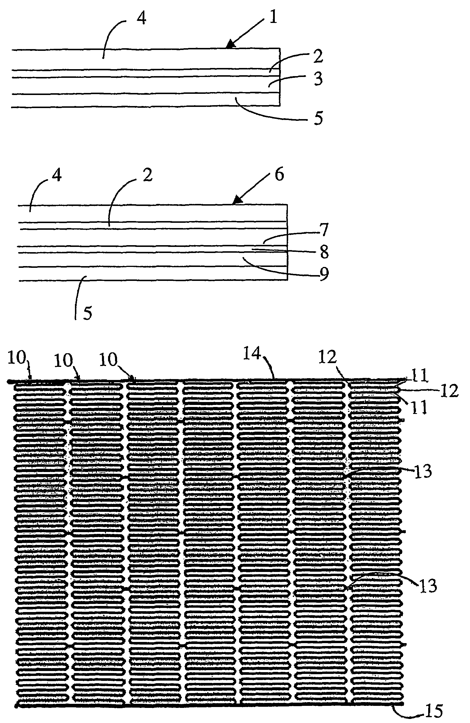
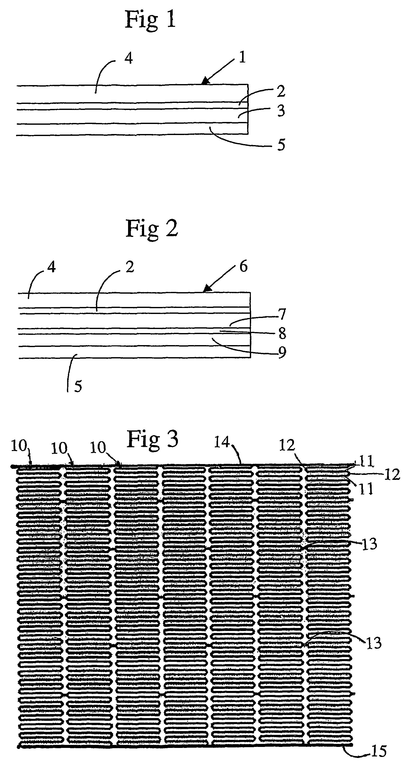
[0015]FIG. 1 shows a heating mat 1 for a thermal target device, a circuit layer 2 consisting of a pattern of aluminum pathways etched onto a substrate layer 3 of polyester. The circuit layer 2, which will be described in greater detail below, is arranged so as to conduct current, whereupon heat is generated. On top of the circuit layer 2 there is disposed a layer 4 of a plastic film, which stabilizes and protects the aluminum circuit. The plastic film can be dulled to reduce reflections from its surface. The plastic film is made of, e.g. polyethylene or polyester. A layer 5 of heat-insulating material is disposed on the side of the substrate layer 3 facing the circuit layer 2 in order to prevent heat from radiating out from the rear of the mat. The heat-insulating material is made of, e.g. foam rubber. The circuit layer 2 is electrically connected by means of one or more return conductors (not shown) at one edge of the mat by means of, e.g. connectors (not shown). At an opposite edg...


PUM


Abstract

A target device for firing practice. At least one thermal target surface is heated by an electrically current passing through same. The thermal target surface includes a number of current coils arranged so as to conduct the current from a first area of the target surface to a second area. Each current coil includes current conductors disposed essentially in parallel with one another at a first distance from one another. The current conductors are connected to one another at their ends so that they form the current coil from the first area to the second area. Proximate current coils are mutually connected via bridges.

Description

TECHNICAL AREA[0001]This invention concerns a target device for firing practice as per the preamble to claim 1.STATE OF THE ART[0002]In firing practice and tactical exercises involving weapons equipped with thermal sights, target figures that exhibit as realistic a signature as possible are needed. As a result, target surfaces whose heat radiation properties are as similar to those of the actual targets as possible are sought after. The target surfaces may resemble, e.g. tank targets.[0003]Known thermal targets constructed of modules comprise a foil of relatively high resistivity. To achieve the desired heat radiation, there is a need for a corresponding relatively high electrical voltage, which is undesirable from a safety standpoint. The modules can alternatively be equipped with a low-resistivity foil such as aluminum foil, and electrical current is applied at low voltage and high amperage. However, this design requires that a transformer be disposed at the target, and that extre...

Claims


Application Information

Patent Timeline
IPC IPC(8): F41J2/02
CPCF41J2/02
Inventor ANDREN, ROBERTLARSSON, RONNIE
Owner SAAB AB
Why Eureka
Try Eureka