Method for performing silicon melt infiltration of ceramic matrix composites

a ceramic matrix and composite technology, applied in the field of ceramic matrix composite manufacturing, can solve the problems of accelerating corrosion of si and sic within the preform, and achieve the effect of reducing the time required to melt infiltrate the cmc preform and reducing the likelihood of molten silicon attacking the preform

Inactive Publication Date: 2006-07-27
GENERAL ELECTRIC CO
View PDF7 Cites 36 Cited by
  • Summary
  • Abstract
  • Description
  • Claims
  • Application Information

AI Technical Summary

Benefits of technology

[0009] In accordance with an exemplary embodiment of this invention, a fiber-reinforced CMC preform is melt-infiltrated by dipping the preform into a bath of molten silicon. In one exemplary embodiment, the parts are suspended from a graphite holder in a vacuum and/or inert atmosphere furnace. The holder an

Problems solved by technology

Boron is known to cause accelerated corrosion of the Si and SiC within

Method used


Image

  • Method for performing silicon melt infiltration of ceramic matrix composites
  • Method for performing silicon melt infiltration of ceramic matrix composites

Examples


Embodiment Construction

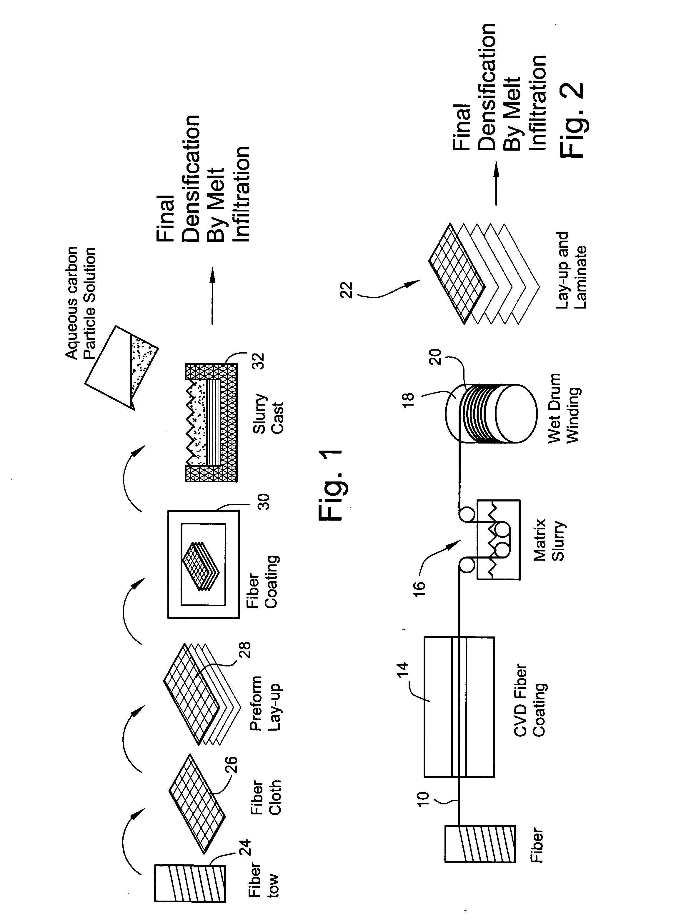
[0015]FIG. 1 is a schematic diagram of a conventional prepreg process used in the manufacture of ceramic matrix composites. After the fiber tow 10 is wound from a drum 12, it passes through a vessel 14 where a ceramic fiber coating is applied to the tow via a known chemical vapor deposition (CVD) process. This coating serves to protect the fibers during composite processing and provides a low strength fiber-matrix interface, thereby enabling the fiber matrix debonding and fiber pull-out “toughening” mechanisms. CMC's typically in the past used carbon as the fiber coating, but have since incorporated boron nitride or silicon-doped boron nitride for increased oxidation resistance. Following fiber coating, the fiber tow 10 is pulled through a vessel 16 containing a slurry including the preform matrix constituents (SiC and carbon particulate, binders and solvents), and then wound on a drum 18 to form a unidirectional pre-impregnated, i.e., “pre-preg,” tape 20. The tape is then dried, re...


PUM

PropertyMeasurementUnit
Temperatureaaaaaaaaaa
Lengthaaaaaaaaaa

Abstract

A method of melt infiltrating a fiber-reinforced ceramic matrix composite preform includes (a) dipping the preform into a bath of molten Silicon; (b) leaving the preform in the bath for a predetermined time; (c) withdrawing the preform from the bath; and (d) cooling the preform.

Description

BACKGROUND OF THE INVENTION [0001] This invention relates to the manufacture of ceramic matrix composites and specifically, to a method for melt infiltrating a fiber-reinforced ceramic matrix composite (CMC) with molten silicon. [0002] A variety of processing schemes have been developed for the fabrication of MI-CMCs. One process is known as the “prepreg process” and the other is known as the “slurry cast” process. [0003] The first step in the “prepreg” process is the application of a fiber coating via chemical vapor deposition (CVD). The fiber coating serves to protect the fibers during composite processing and provides a low-strength fiber-matrix interface, thereby enabling fiber-matrix debonding and fiber pull-out “toughening” mechanisms. CMCs have typically in the past used carbon as the fiber coating, but have since incorporated boron nitride or silicon-doped boron nitride for increased oxidation resistance. [0004] Following fiber coating, the fiber tow is pulled through a slur...

Claims


Application Information

Patent Timeline
IPC IPC(8): B28B19/00B29C49/00
CPCC04B35/573C04B35/62884C04B35/806C04B2235/3826C04B2235/614C04B2235/616C04B35/62868C04B2235/422C04B2235/5268C04B2235/6567C04B35/80
Inventor GRAY, PAUL EDWARD
Owner GENERAL ELECTRIC CO
Why Eureka
Try Eureka