Split flow process and apparatus

a technology of gas separation and apparatus, applied in separation processes, hydrogen sulfides, sulfur compounds, etc., can solve the problems of limiting the degree of optimization of this process, unable to achieve stringent emission standards with a standard regenerator-absorber system, and insufficient acid gas removal efficiency

Active Publication Date: 2008-05-27
FLUOR TECH CORP
View PDF12 Cites 58 Cited by
  • Summary
  • Abstract
  • Description
  • Claims
  • Application Information

AI Technical Summary

Problems solved by technology

However, in many circumstances the extent of the acid gas removal efficiency is not satisfactory, and especially where the acid gas is carbon dioxide, stringent emission standards can often not be achieved with a standard regenerator-absorber system.
However, increased corrosivity and solvent degradation often limit the degree of optimization for this process.
However, the reduction in energy consumption is relatively low due to thermodynamic inefficiencies in stripping (mainly because of variations in the solvent composition as it circulates within the split loop).
However, the modifications to improve energy use and lower solvent circulation generally require a substantial modification in the configuration of the main regenerator, and the installation of a side-regenerator, both of which may result in substantial costs and significant down-time of an existing absorber-regenerator system.
However, due to the use of recycle gas and the use of a secondary regenerator column, retrofitting of existing absorber-regenerator combinations may be relatively expensive and time consuming.
Therefore, although various improvements to the basic configuration of an absorber-regenerator process are known in the art, all or almost all of them suffer from one or more disadvantages.

Method used


Image

  • Split flow process and apparatus
  • Split flow process and apparatus
  • Split flow process and apparatus

Examples


Embodiment Construction

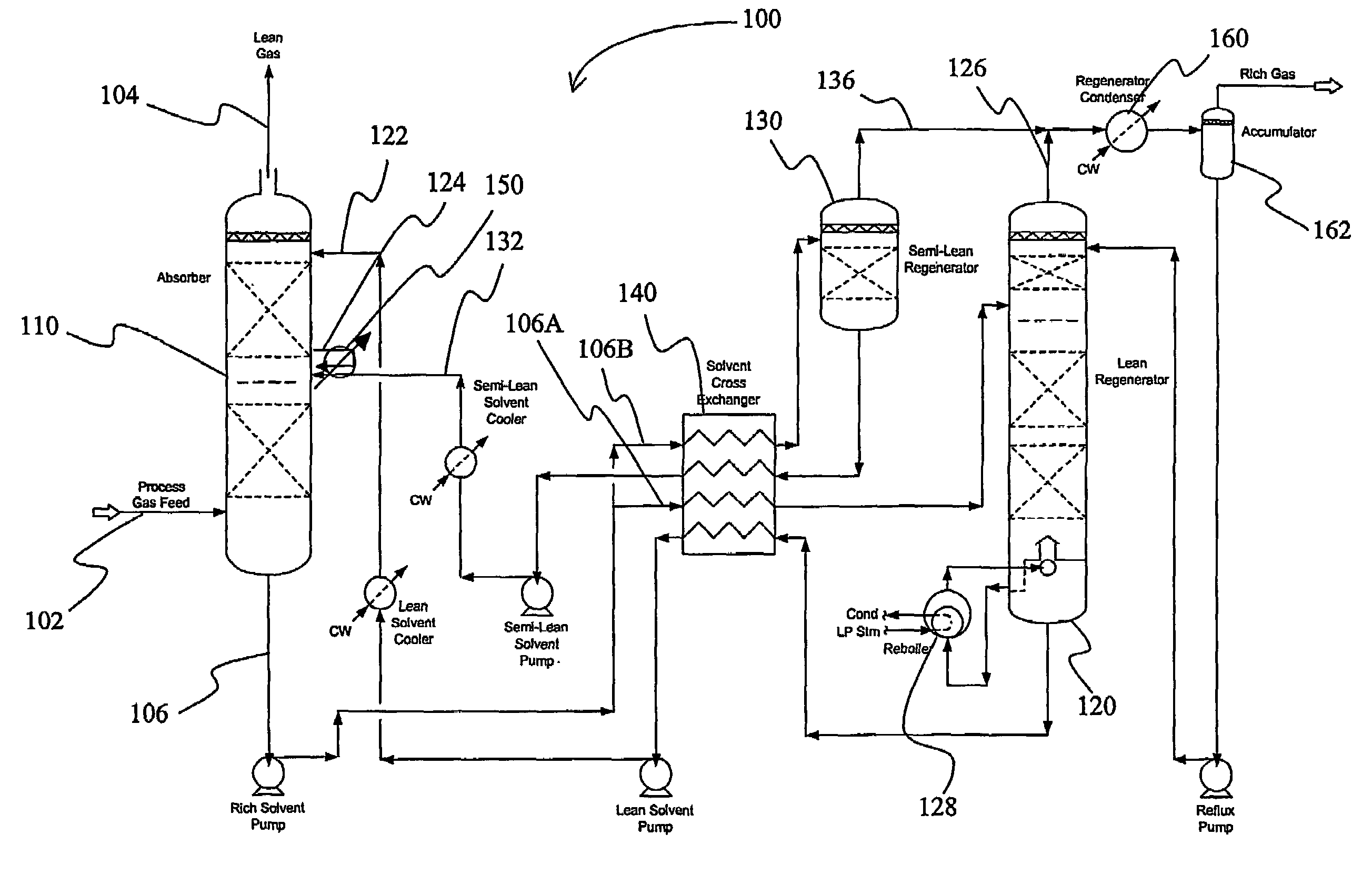
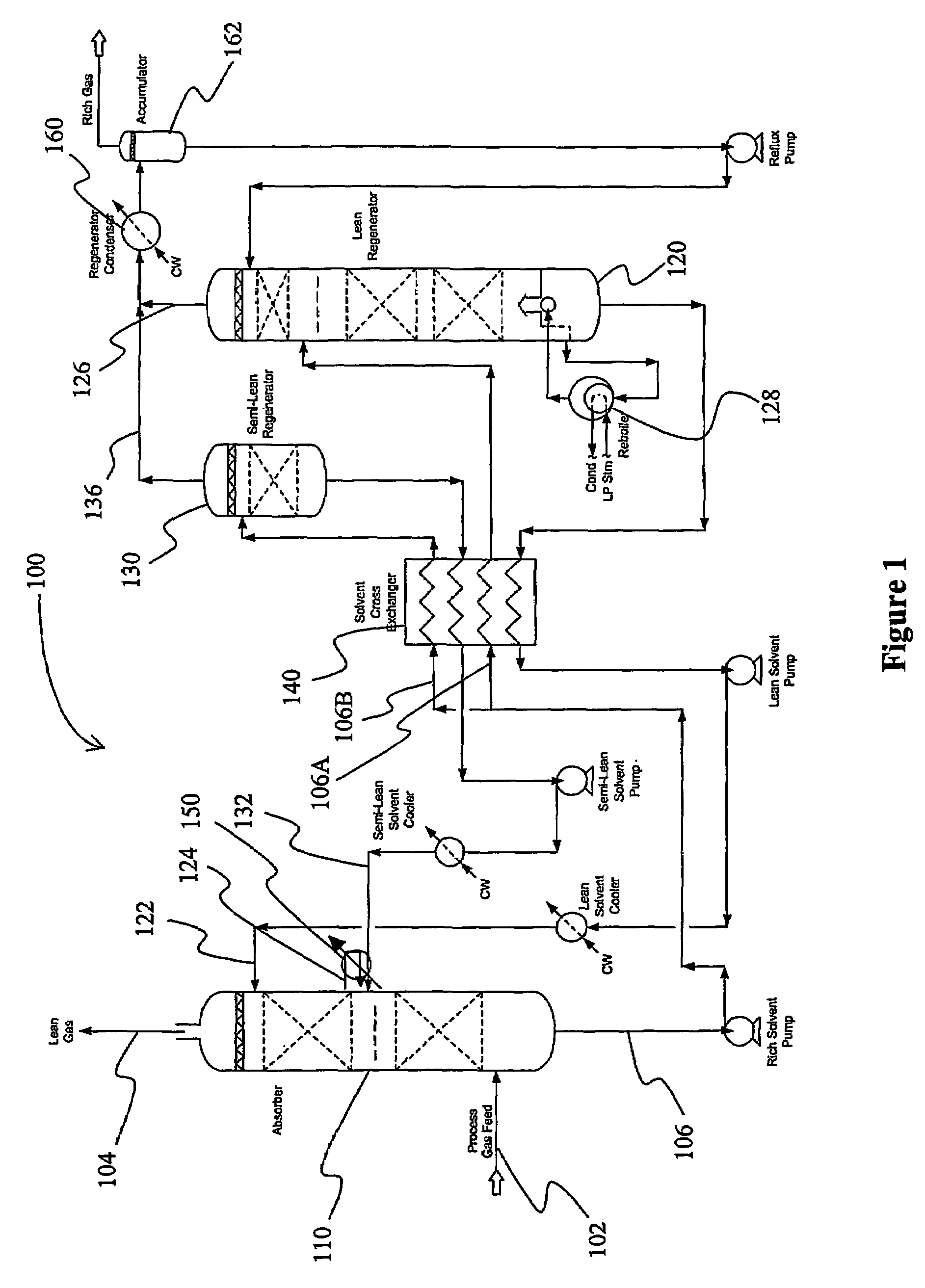
[0022]The inventors discovered that configurations and methods in which a lean solvent and a semi-lean solvent are employed for removal of a gaseous component (and especially an acid gas) from a feed gas can be operated with improved efficiency when the lean solvent and semi-lean solvent are produced in separate regenerators. Unexpectedly, despite the increased solvent flow rate requirements of such configurations, the inventors discovered that all or almost all of the contemplated configurations provide significant economic advantages that are predominantly due to reducing heating energy demand.

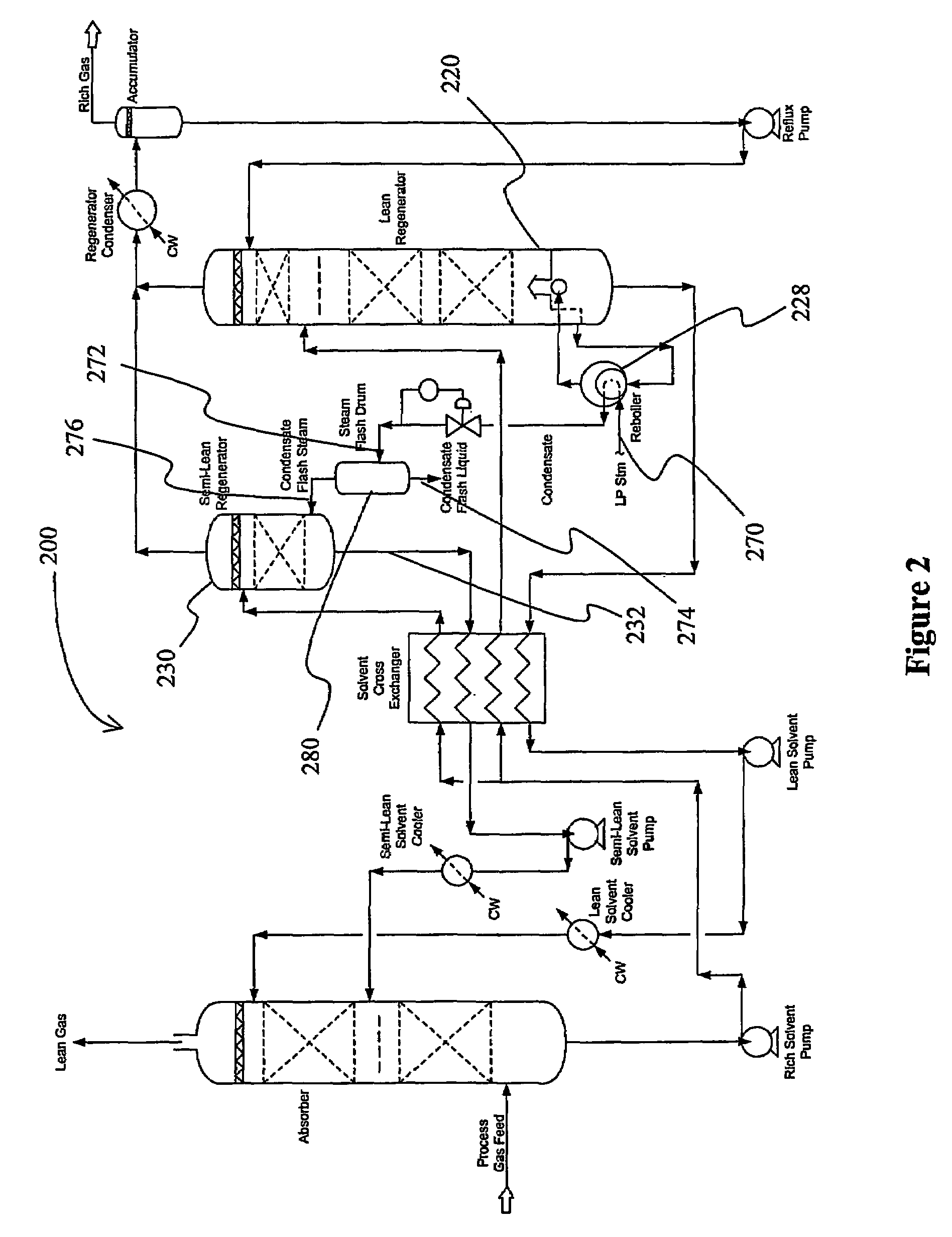
[0023]Moreover, the inventors discovered that various operational aspects of contemplated configurations may be even further improved when (a) the semi-lean solvent regenerator is stripped with steam flashed from condensate produced in the lean regenerator reboiler, (b) an absorber intercooler is employed that maintains a lower solvent temperature across the absorber, and / or (c) where the he...


PUM

PropertyMeasurementUnit
flow ratesaaaaaaaaaa
pressureaaaaaaaaaa
pressureaaaaaaaaaa

Abstract

An acid gas removal plant includes an absorber that provides a rich solvent to two regenerators that independently generate a lean and a semi-lean solvent, wherein the semi-lean solvent is produced in one of the regenerators using heat and / or steam derived from the other regenerator. Further heat integration is particularly contemplated with power plants in which the power plant provides high-level heat to the acid gas removal plant and wherein the power plant receives low-level heat from the acid gas removal plant.

Description

[0001]This application claims the benefit of U.S. provisional application with Ser. No. 60 / 393,595, which was filed on Jul. 3, 2002, and of U.S. provisional application with Ser. No. 60 / 467,719, which was filed May 2, 2003, both of which are incorporated herein by reference.FIELD OF THE INVENTION[0002]The field of the invention is gas processing, especially as it relates to removal of acid gas components of various feed gases, and particularly flue gases.BACKGROUND OF THE INVENTION[0003]Various configurations and methods are known in the art to remove acid gas from a process gas (e.g., various distillation-, adsorption- and absorption processes), and among those regenerator-absorber systems are frequently employed as a relatively robust and cost-efficient gas purification system.[0004]In a typical regenerator-absorber system, gas is contacted in an absorber in a counter-current fashion and the acid gas (or other gaseous component) is at least partially absorbed by a lean solvent to ...

Claims


Application Information

Patent Timeline
Patent Type & Authority Patents(United States)
IPC IPC(8): B01D53/14B01D53/62B01D3/06
CPCB01D53/1406B01D53/1425B01D53/1456B01D2257/504B01D2259/652
Inventor REDDY, SATISHSCHERFFIUS, JEFFREYGILMARTIN, JOHNFREGUIA, STEFANO
Owner FLUOR TECH CORP
Why Eureka
Try Eureka