Check patentability & draft patents in minutes with Patsnap Eureka AI!

Self-adjusting masking plug for complex parts

a masking plug and complex technology, applied in the direction of additive manufacturing apparatus, liquid surface applicators, spraying apparatus, etc., can solve the problems of masking plugs not fitting properly into the masking area, many times the hole, bore, void, etc., and achieve the effect of improving performance characteristics

Active Publication Date: 2008-05-27
NORTHROP GRUMMAN SYST CORP
View PDF13 Cites 0 Cited by
  • Summary
  • Abstract
  • Description
  • Claims
  • Application Information

AI Technical Summary

Benefits of technology

The present invention provides a self-adjusting masking plug that can be inserted into complex parts to mask them. The masking plug has a wishbone spring that can expand or compress depending on the tolerances of the part. The masking plug can be securely maintained within the part due to the forces exerted by its perimeter walls against the part. The masking plug can also have an adjustable seam and a common annular space between its inner walls. Additionally, the masking plug can have at least one overhang panel and multiple self-adjusting masking plugs. The masking plug is made from selective laser sintering or NYLON 12 or (11. The technical effects of the present invention are better performance characteristics and improved efficiency in masking complex parts.

Problems solved by technology

Also, since the quality of the conventional technique of masking is dependent on the individual performing the job, the results (i.e., quality of mask job) is prone to varying.
A drawback with masking plugs, however, is that many times the holes, bores, valleys, voids, journals, cylinders, sealing surfaces, etc.
And as a result, many times the masking plug does not properly fit into the masked area.
In this situation, the coating is not blocked by the masking plug and areas intended to be masked end up being inadvertently coated and the removal of the inadvertent coated areas adds cost to the manual labor component.

Method used


Image

  • Self-adjusting masking plug for complex parts
  • Self-adjusting masking plug for complex parts
  • Self-adjusting masking plug for complex parts

Examples


Embodiment Construction

[0025]The particulars shown herein are by way of example and for purposes of illustrative discussion of the embodiments of the present invention only and are presented in the cause of providing what is believed to be the most useful and readily understood description of the principles and conceptual aspects of the present invention. In this regard, no attempt is made to show structural details of the present invention in more detail than is necessary for the fundamental understanding of the present invention, the description taken with the drawings making apparent to those skilled in the art how the several forms of the present invention may be embodied in practice.

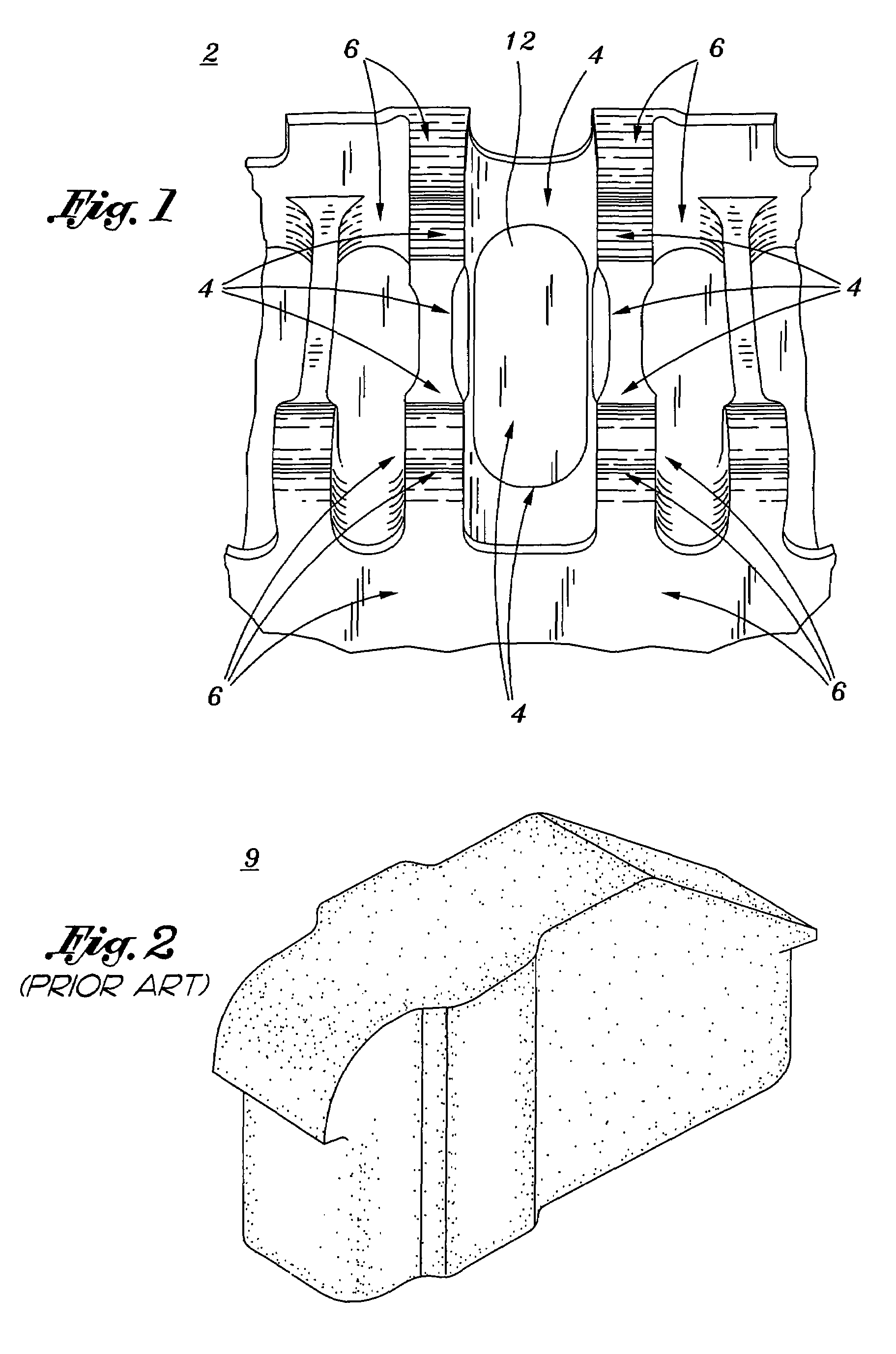
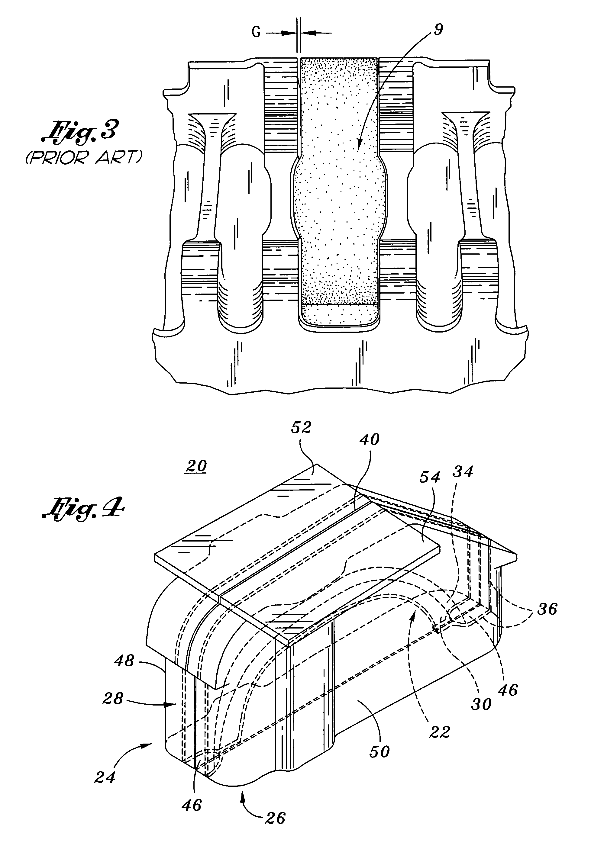
[0026]FIG. 1 shows an exemplary complex part 2, according to an aspect of the present invention. The complex part 2 includes a region 4 in which it is desired to not have a coating applied. The complex part 2 further includes areas 6 which are intended to be coated. For example, the exemplary complex part 2 shown in FIG. ...


PUM


Abstract

A self-adjusting masking plug is provided which is adapted to be received in a region of a complex part intended to be masked. The plug has a body adapted to be received within a region of the part intended to be masked. The body includes a first body half having at least one first perimeter wall conforming to a first portion of the intended region to be masked; a second body half having at least one second perimeter wall conforming to a second portion of the intended region to be masked; and a wishbone spring formed internally within the body such that it interconnects the first and second body halves. The wishbone spring includes a first half inner wall transversely spanning and interconnecting portions of the at least one first perimeter wall; a second half inner wall transversely spanning and interconnecting portions of the at least one second perimeter wall; and a common rib interconnecting the first and second inner walls. The plug is adapted to expand or compress depending on the tolerances of the part within the part.

Description

CROSS-REFERENCE TO RELATED APPLICATIONS[0001]Not ApplicableSTATEMENT RE: FEDERALLY SPONSORED RESEARCH / DEVELOPMENT[0002]Not ApplicableBACKGROUND OF THE INVENTION[0003]1. Field of the Invention[0004]The present invention relates to masking plugs for complex parts. In particular, the present invention relates to self-adjusting masking plugs for complex parts which are adapted to be fit into similarly dimensioned parts which have the same dimensions, but which have varying tolerances.[0005]2. Background of the Invention[0006]When a complex aerospace, defense, manufacturing, or industrial machine part or the like is manufactured, the part may have areas which are intended to have exposed machine surfaces as well as surfaces which are coated with various coating materials (primer, paints, powder coat, rust inhibitors, sealants, etc.) Typically, the portion of the part intended to be left exposed without coating is masked with tape and materials, such as plastic sheets or paper. This conve...

Claims


Application Information

Patent Timeline
Patent Type & Authority Patents(United States)
IPC IPC(8): B05C21/00
CPCB05B15/0481B05B15/0456B33Y80/00B05B12/24B05B12/29
Inventor HUSMANN, CHRISTOPHER H.JAFFKE, RALPH E.
Owner NORTHROP GRUMMAN SYST CORP
Features
  • R&D
  • Intellectual Property
  • Life Sciences
  • Materials
  • Tech Scout
  • Unparalleled Data Quality
  • Higher Quality Content
  • 60% Fewer Hallucinations
Learn More