Color display substrate, color filter substrate, color luminescent substrate, manufacturing method of color display substrate, electro-optical apparatus, electronic device, film-forming method, film-forming apparatus, and display motherboard

a technology of color display substrate and manufacturing method, which is applied in the direction of identification means, instruments, discharge tubes luminescent screens, etc., can solve the problems of high environmental load and high cost of color filter substrate, and achieve the effect of efficient obtaining

Inactive Publication Date: 2008-05-27
KATEEVA
View PDF19 Cites 11 Cited by
  • Summary
  • Abstract
  • Description
  • Claims
  • Application Information

AI Technical Summary

Benefits of technology

[0008]The present invention provides a manufacturing method capable of efficiently obtaining a color display substrate having a plurality of color display elements arranged in matrix arrangements, such as a color filter substrate and color-luminescent substrate.
[0016]The color display substrate can be efficiently obtained by a manufacturing method, which will be described below.
[0039]According to the manufacturing method, each color-dot forming-region constituting the color display element is located at a distance of at least substantially an integral multiple of the first dot pitch in a direction perpendicular to a first base line from the first base line, so that positional data of the color-dot forming-region can be prescribed by the first dot pitch, facilitating the design.
[0042](A) The region where the color dots are formed of the color display element may be located at a distance of substantially an integral multiple of a second dot pitch in a direction perpendicular to a second base line from the second base line perpendicular to the first base line. By such a setting, not only from the first base line but also from the second base line, positional data of the color-dot forming-region can be prescribed by the second dot pitch, facilitating the design.

Problems solved by technology

In this manufacturing method, the photolithography process has to be repeated for each color, and since an unnecessary portion is removed for patterning each color, losses in a photoresist are produced, resulting in a color filter with high cost and high environmental loading.

Method used


Image

  • Color display substrate, color filter substrate, color luminescent substrate, manufacturing method of color display substrate, electro-optical apparatus, electronic device, film-forming method, film-forming apparatus, and display motherboard
  • Color display substrate, color filter substrate, color luminescent substrate, manufacturing method of color display substrate, electro-optical apparatus, electronic device, film-forming method, film-forming apparatus, and display motherboard
  • Color display substrate, color filter substrate, color luminescent substrate, manufacturing method of color display substrate, electro-optical apparatus, electronic device, film-forming method, film-forming apparatus, and display motherboard

Examples


first embodiment

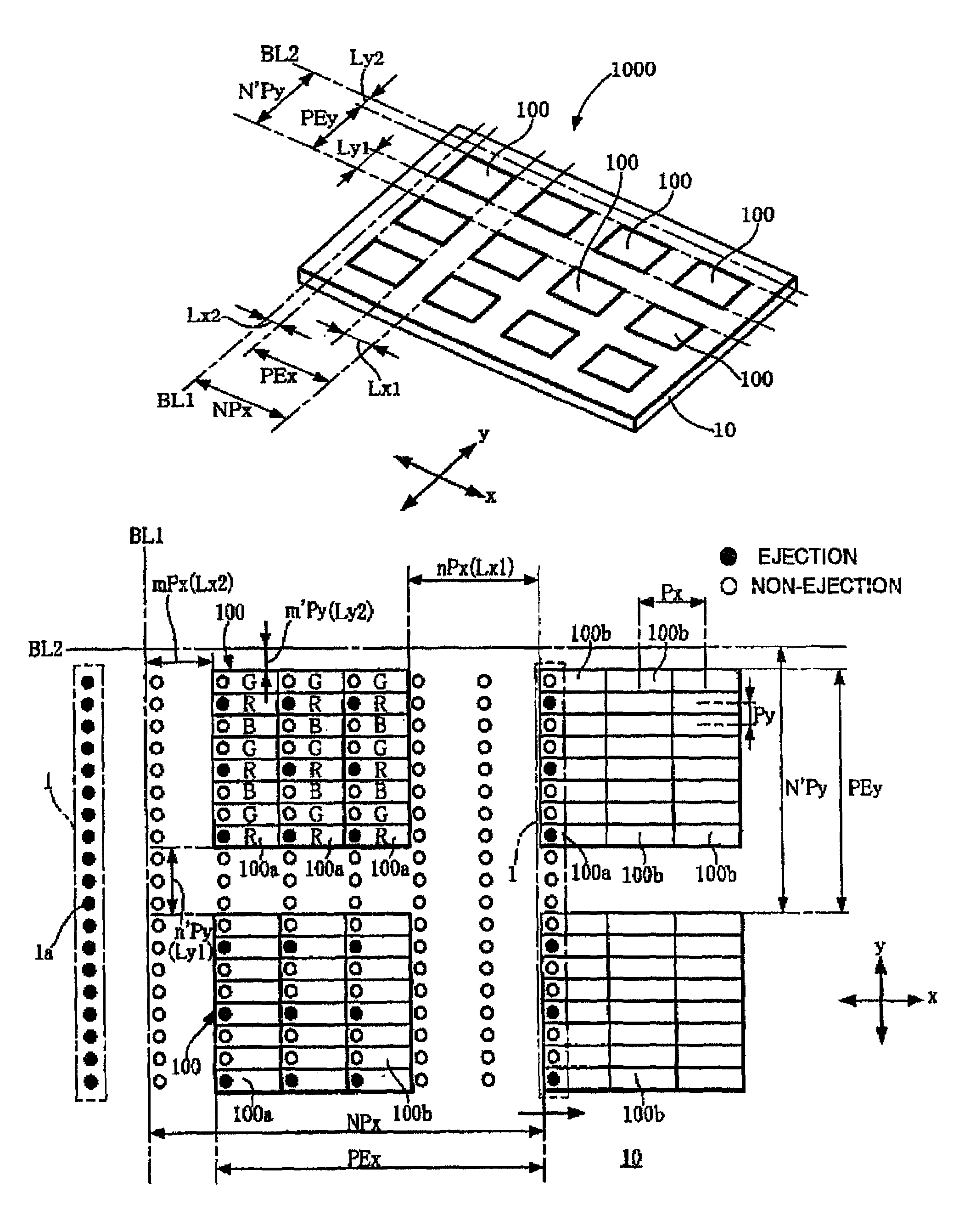
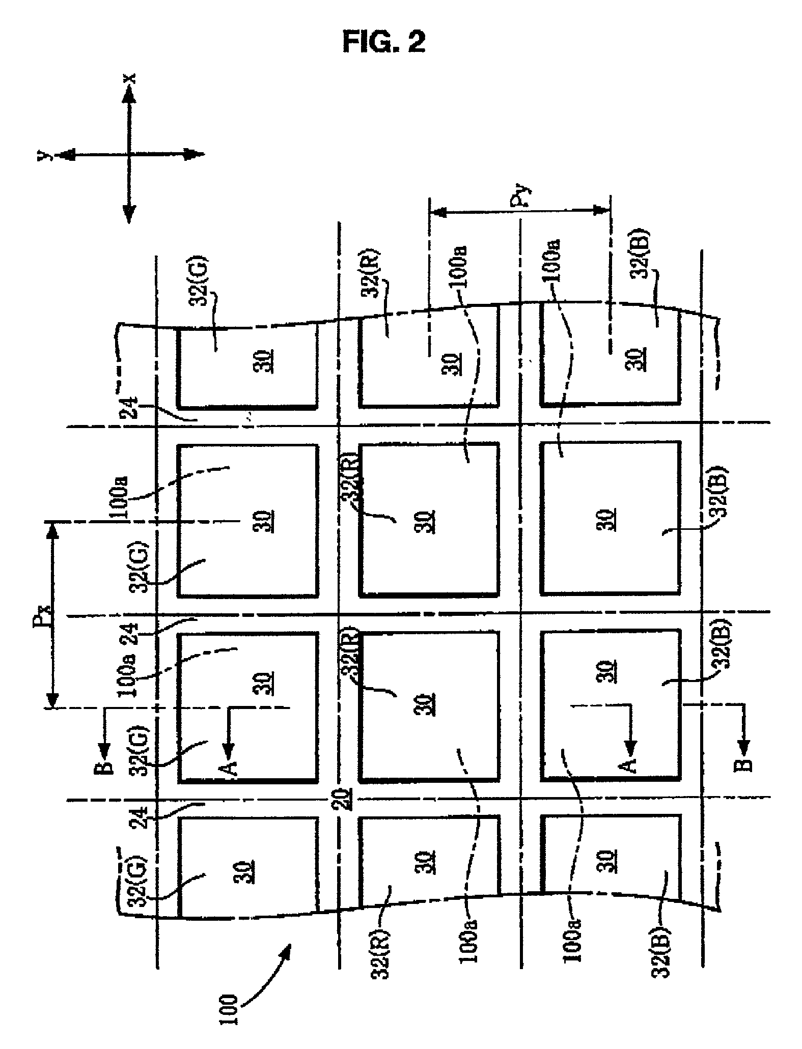
[0081]FIG. 1 is a perspective view schematically showing a color filter substrate as an example of a color display substrate (display motherboard) applied in the present invention; FIG. 2 is a plan view of a significant part of a color filter element (unit constituting the display) forming the color filter substrate; and FIG. 3 is a sectional view taken along plane A—A of FIG. 2.

[0082](Overview of Color Filter Substrate)

[0083]First, an overview of a color filter substrate 1000 will be described. The color filter substrate 1000 is of a light-transmission type and includes a transparent substrate 10 made of glass or plastic, and plural color filter elements 100 formed on the substrate 10 in matrix arrangement. Plural color filters can be obtained by cutting the color filter substrate 1000 at predetermined positions afterward.

[0084]The color filter element 100 according to an embodiment, as shown in FIGS. 2 and 3, includes a transparent substrate 10, a light-shielding region 20, which ...

second embodiment

[0143]FIG. 8 is a schematic perspective view of a color luminescent substrate (display motherboard) as an example of the color display substrate applied in the present invention; FIG. 9 is a plan view of a significant part of a color luminescent element (unit constituting the display) forming the color luminescence substrate; and FIG. 10(D) is a sectional view taken along plane C—C of FIG. 9.

[0144](Overview of Color Luminescence Substrate)

[0145]An overview of a color luminescent substrate 2000 according to a second embodiment will be described. The color luminescent substrate 2000 includes a transparent substrate 104 and plural color luminescent elements 200 formed on the substrate 104 in a matrix pattern. A plurality of color illuminators can be obtained by cutting the color luminescence substrate 2000 at predetermined positions afterward.

[0146]The color luminescent element 200 according to the embodiment, as shown in FIGS. 9 and 10(D), includes the transparent substrate 104, a ban...

third embodiment

[0204](Electro-Optical Apparatus)

[0205]FIG. 13 is a sectional view of a significant part of a color liquid-crystal display 1100, as an example of the electro-optical apparatus, in which a color filter 1000A is assembled, which is obtained from the color filter substrate 1000 according to the first embodiment.

[0206]The color liquid-crystal display 1100 is configured by combining the color filter 1000A with an opposing substrate 80, and enclosing a liquid-crystal composition 70 between them. On the internal surface of the one substrate 80 of the liquid-crystal display 1100, TFT (thin-film transistor) elements (not shown) and pixel electrodes 52 are formed in a matrix pattern. As the other substrate, the color filter 1000A is placed so as to arrange the red, green, and blue colored layers at positions opposing the pixel electrodes 52. On the respective opposing surfaces of the substrate 80 and the color filter 1000A, oriented films 60 and 62 are formed. The rubbing treatment is perform...


PUM

PropertyMeasurementUnit
thicknessaaaaaaaaaa
thicknessaaaaaaaaaa
contact angleaaaaaaaaaa

Abstract

The invention provides a color display substrate having plural color display elements arranged in a matrix pattern, and a manufacturing method to efficiently obtain a color filter substrate and color luminescent substrate, for example. A manufacturing method of a color display substrate includes the step of forming plural color dots by selectively ejecting liquid droplets from nozzles in accordance with input data. The plural color dots constitute plural pixels, which constitute plural color filter elements arranged in a matrix pattern. The plural color dots have a first dot pitch in a direction perpendicular to a first base line. Each of the plural color dots is formed to lie at a distance of at least substantially an integral multiple of the first dot pitch from the first base line.

Description

BACKGROUND OF THE INVENTION[0001]1. Field of Invention[0002]The present invention relates to a color display substrate, a color filter substrate, a color luminescent substrate, a manufacturing method of the color display substrate, an electro-optical apparatus, an electronic device, a film-forming method, a film-forming apparatus, and a display motherboard.[0003]2. Description of Related Art[0004]Recently, along with advancements in personal computers, especially in portable personal computers and portable information devices, the demand for liquid crystal color displays has strongly increased. Accordingly, an urgent need exists to establish a method of providing an excellent display at a fair price. In order to provide environmental protection, conversion into, and enhancement of, methods to reduce environmental loading are also demanded.[0005]The following is a related art method for manufacturing a color filter.[0006]In the method, first, a chrome thin film is patterned by photol...

Claims


Application Information

Patent Timeline
Patent Type & Authority Patents(United States)
IPC IPC(8): H01J1/62H01J63/04B41J2/01G02B5/20G02F1/1335G09F9/30G09F9/35H01L27/32H01L51/52
CPCG02F1/133514H01L27/3211G02F1/133516H01L27/322H01L27/3295H01L51/5284H10K59/35H10K59/38H10K59/122H10K50/865G02F1/1335
Inventor ARUGA, HISASHIKATAGAMI, SATORUYAMADA, YOSHIAKIKIGUCHI, HIROSHI
Owner KATEEVA
Why Eureka
Try Eureka