Beam shaping device

a beam shaping and beam technology, applied in the field of beam shaping devices, can solve the problems of lowering recording and reproducing accuracy, inability to obtain sufficient laser power to achieve satisfactorily accurate recording and reproducing, and low output of currently available blue semiconductor lasers, etc., to achieve good performance, easy production, and high shaping magnification

Inactive Publication Date: 2008-05-27
KONICA MINOLTA OPTO
View PDF15 Cites 2 Cited by
  • Summary
  • Abstract
  • Description
  • Claims
  • Application Information

AI Technical Summary

Benefits of technology

[0012]In view of the conventionally experienced inconveniences and disadvantages described above, it is an object of the present invention to provide a beam shaping device that is easy to produce and that affords a high shaping magnification but that nevertheless offers good performance.
[0023]According to the present invention, a beam shaping device has a circular-arc cylindrical surface and a non-circular-arc cylindrical surface of which both have a curvature only in the minor-axis direction of the cross section of an elliptic beam, and is so constructed as to fulfill prescribed conditions with respect to the center thickness, surface shapes, and other features. This makes it possible to realize an easy-to-produce, lightweight, and compact beam shaping device that offers high performance and that in addition affords a high shaping magnification. Using a beam shaping device according to the present invention in an optical pickup apparatus contributes to enhanced recording and reproducing accuracy and to enhanced laser light use efficiency. This makes it possible to cope with a blue laser.

Problems solved by technology

If this divergent beam as it is emitted is made to converge with an objective lens, it may illuminate only part of the circular recording region, or it may unnecessarily illuminate an area outside the recording region, either way leading to lowered recording and reproducing accuracy.
Nevertheless, the outputs of currently available blue semiconductor lasers are so low that it is impossible to obtain sufficient laser power to achieve satisfactorily accurate recording and reproducing.
This requires a collimator lens, causing the following and other inconveniences.
In a case where, for example, a blue laser is used, disposing a collimator lens on the light-source side of a beam shaping prism makes it impossible to move the collimator lens for the purpose of correcting the spherical aberration resulting from errors in the disk substrate.
Giving a beam shaping device an anamorphic surface as proposed in Patent Publication 1 makes it difficult to produce the mold for forming the beam shaping device.
This makes the beam shaping device unsuitable for mass production and expensive to produce.
On the other hand, the beam shaping device proposed in Patent Publication 2 does not afford a satisfactorily high shaping magnification, and thus does not offer sufficiently high light use efficiency for recording and reproducing.

Method used


Image

  • Beam shaping device
  • Beam shaping device
  • Beam shaping device

Examples


examples

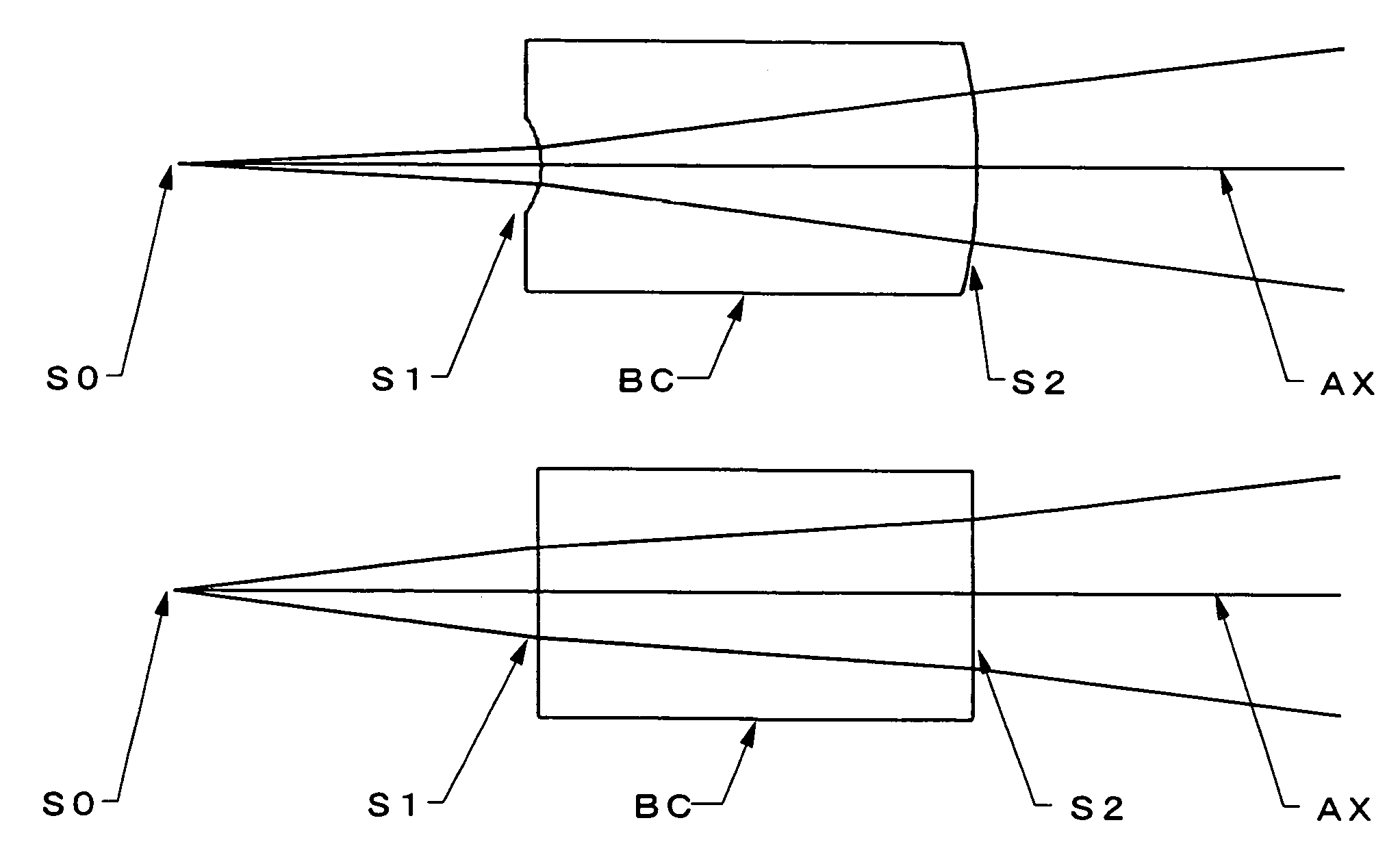
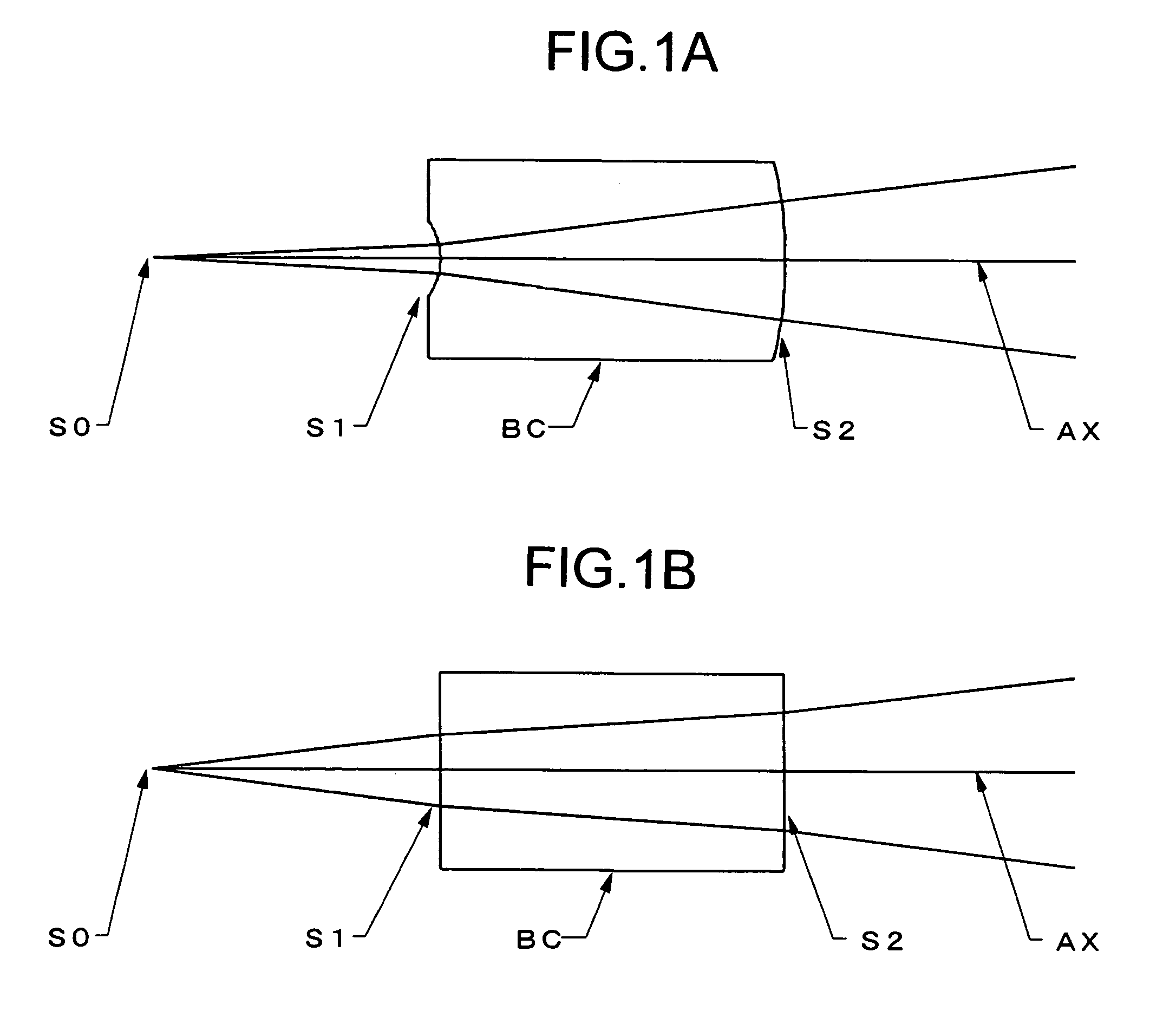
[0085]Hereinafter, the optical construction and other features of practical examples of beam shaping devices embodying the present invention will be presented with reference to their construction data and other data. Examples 1 to 14 presented below are different numerical examples of the optical construction corresponding to the embodiment (FIG. 1) described above. Of these examples, Example 7 is the numerical example that is identical in shape with the embodiment specifically described above.

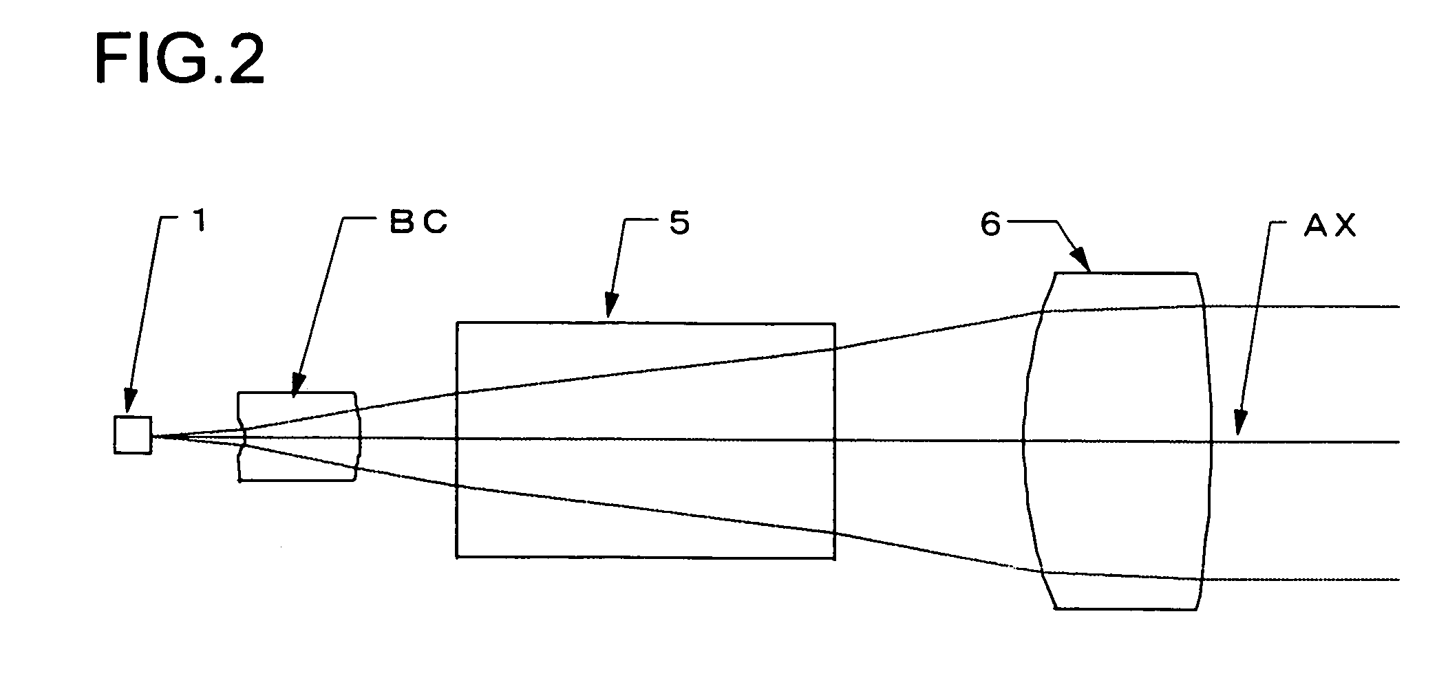
[0086]Tables 1 to 14 show the construction data of Examples 1 to 14, respectively. Table 15 shows the values of the parameters used in each conditional formula as actually observed in each example. In the construction data of each example, λ represents the design wavelength (nm); fx represents the focal length in the X direction; fy represents the focal length in the Y direction; Entrance-Side NAx represents the numerical aperture in the X direction as observed on the side at which the laser l...


PUM

PropertyMeasurementUnit
wavelengthaaaaaaaaaa
radius of curvatureaaaaaaaaaa
focal lengthaaaaaaaaaa

Abstract

In a beam shaping device for converting the laser light emitted from a semiconductor laser light source from an elliptic beam to a circular beam, the light-entrance-side and light-exit-side surfaces of the beam shaping device both have a curvature only in the minor-axis direction of the cross section of the elliptic beam. Of the light-entrance-side and light-exit-side surfaces, one is a circular-arc cylindrical surface and the other is a non-circular-arc cylindrical surface. The beam shaping device fulfills prescribed conditions with respect to the center thickness, surface shapes, and / or other features.

Description

[0001]This application is based on Japanese Patent Applications Nos. 2004-87311 and 2004-193032 filed on Mar. 24, 2004 and Jun. 30, 2004, respectively, the contents of which are hereby incorporated by reference.BACKGROUND OF THE INVENTION[0002]1. Field of the Invention[0003]The present invention relates to a beam shaping device. More particularly, the present invention relates to a beam shaping device that is used, for example, in an optical pickup apparatus to convert the laser light emitted from a semiconductor laser light source from an elliptic beam to a circular beam.[0004]2. Description of Related Art[0005]Optical systems for optical pickups typically use a laser diode as a light source, and the laser beam emitted from a laser diode is a divergent beam having an elliptic sectional shape. If this divergent beam as it is emitted is made to converge with an objective lens, it may illuminate only part of the circular recording region, or it may unnecessarily illuminate an area out...

Claims


Application Information

Patent Timeline
Patent Type & Authority Patents(United States)
IPC IPC(8): G11B7/135G02B26/10G02B3/06G02B13/00G02B27/09G11B7/00G11B7/1378G11B7/1392G11B7/1398
CPCG02B27/0966G11B7/1378G11B7/13922G11B7/1398G02B19/0052G02B19/0014G02B3/06G02B27/09G02B13/00
Inventor TADA, KAZUNARIHASHIMURA, JUNJIORI, YUICHIRO
Owner KONICA MINOLTA OPTO
Why Eureka
Try Eureka