3-dimensional ultrasonographic device

a three-dimensional ultrasonographic and ultrasonographic technology, applied in the direction of instruments, specific gravity measurement, processing detected response signals, etc., can solve the problems of inability to achieve continuous imaging of a wide area, inability to objective and quantitative inspection, and inability to automatically judge, so as to improve the accuracy of internal inspection and widen the inspection area

Active Publication Date: 2008-06-03
KK TOSHIBA
View PDF20 Cites 3 Cited by
  • Summary
  • Abstract
  • Description
  • Claims
  • Application Information

AI Technical Summary

Benefits of technology

[0010]The present invention was made in order to solve the above-described problems and its object is to provide a three-dimensional ultrasonographic device that achieves improved accuracy of internal inspection using an ultrasonic wave, a wider inspection area, and automatic judgment of the inspection.
[0012]The present invention can provide a three-dimensional ultrasonographic device that achieves improved accuracy of internal inspection using an ultrasonic wave, a wider inspection area, and automatic judgment of the inspection.

Problems solved by technology

With the conventional ultrasonic inspection device, a layer structure having a plurality of different acoustic characteristics, and a defect, a void, and peeling in an inspection object having a curved surface can be visualized by using ultrasonic waves, but since judgment on the result imaged by the ultrasonic waves relies on eyes, it is difficult to automatically judge the result and to recognize the positional relation with the inspection object.
Such a conventional ultrasonic inspection device has the following problems.[1] Objective and quantitative inspection is difficult since internal inspection relies on a person's observation of the imaged result.[2] Brightness of an image varies at different depths of the inspection object due to the influence of a surface-reflected wave in the inspection object, the attenuation of the ultrasonic wave in the inspection object, and the like.[3] Continuous imaging of a wide area is not possible due to the limited size of the ultrasonic transducer.[4] If the periphery of an inspection area of the inspection object is uneven, the ultrasonic wave reflected on the uneven portion of the periphery deteriorates image quality of an internal image of the inspection object.[5] It is not possible to automatically determine whether abnormality exists or not, based on position and shape information of the defect obtained from the three-dimensional imaging of the interior of the inspection object.

Method used


Image

  • 3-dimensional ultrasonographic device
  • 3-dimensional ultrasonographic device
  • 3-dimensional ultrasonographic device

Examples


Embodiment Construction

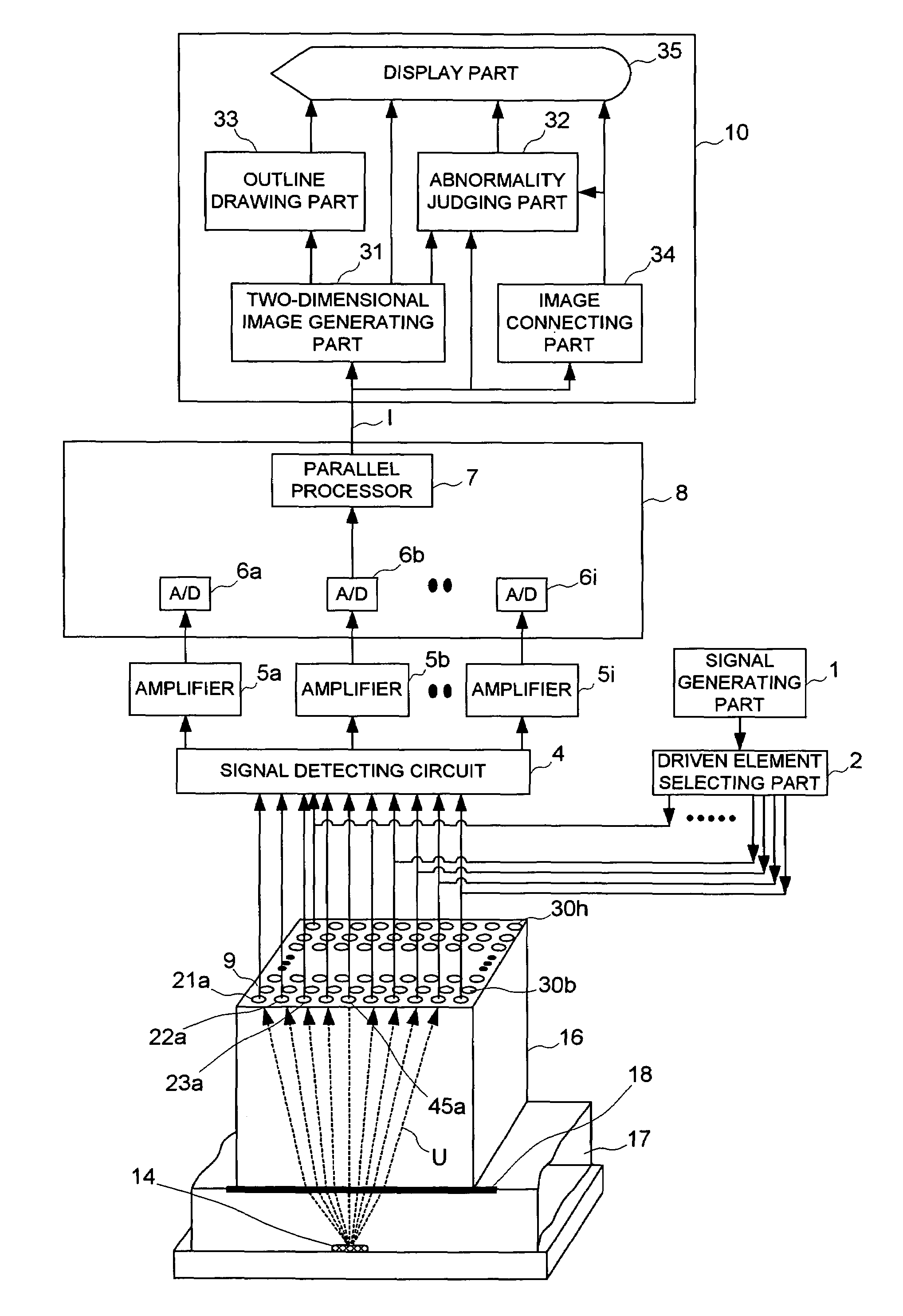
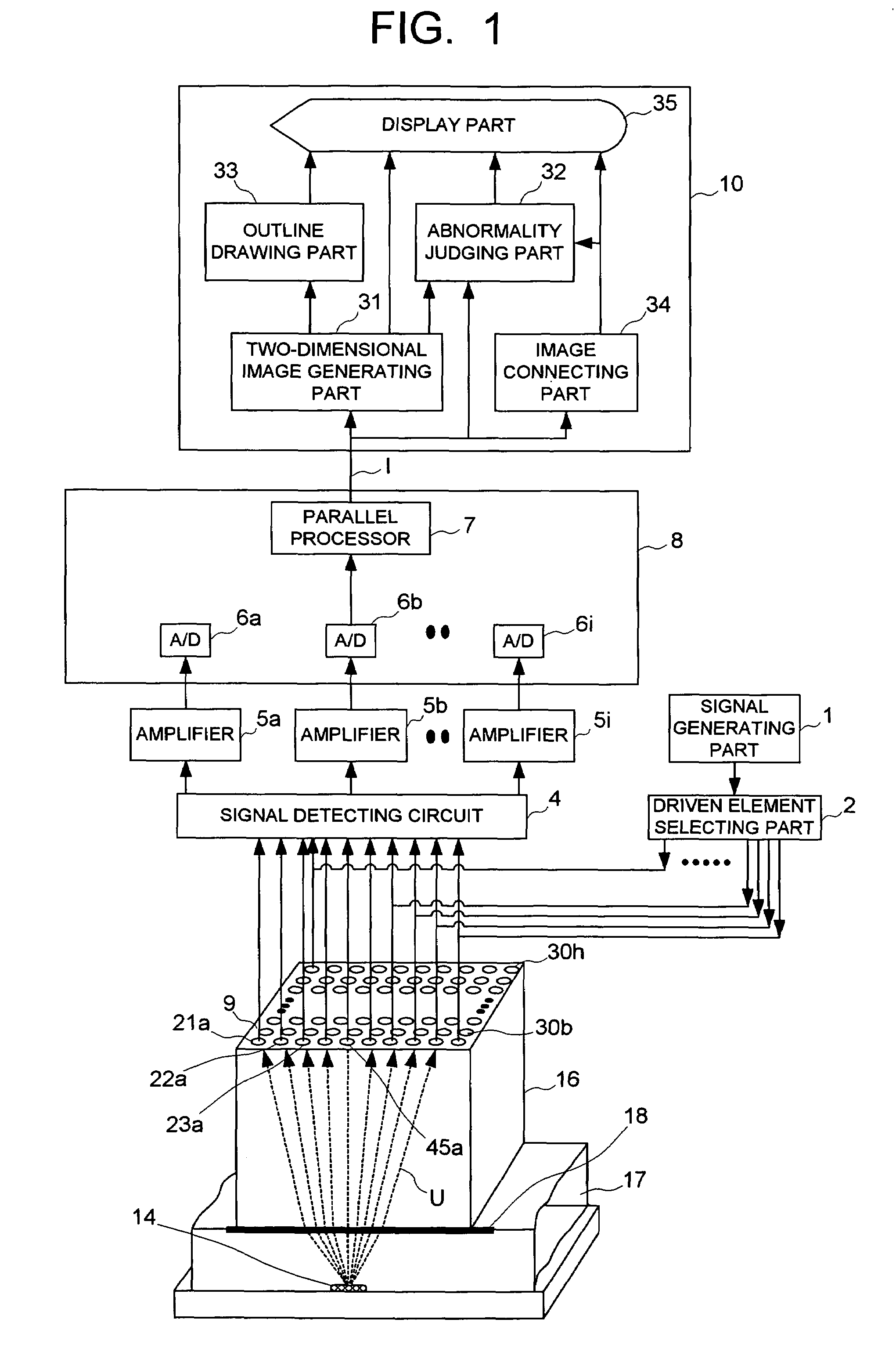
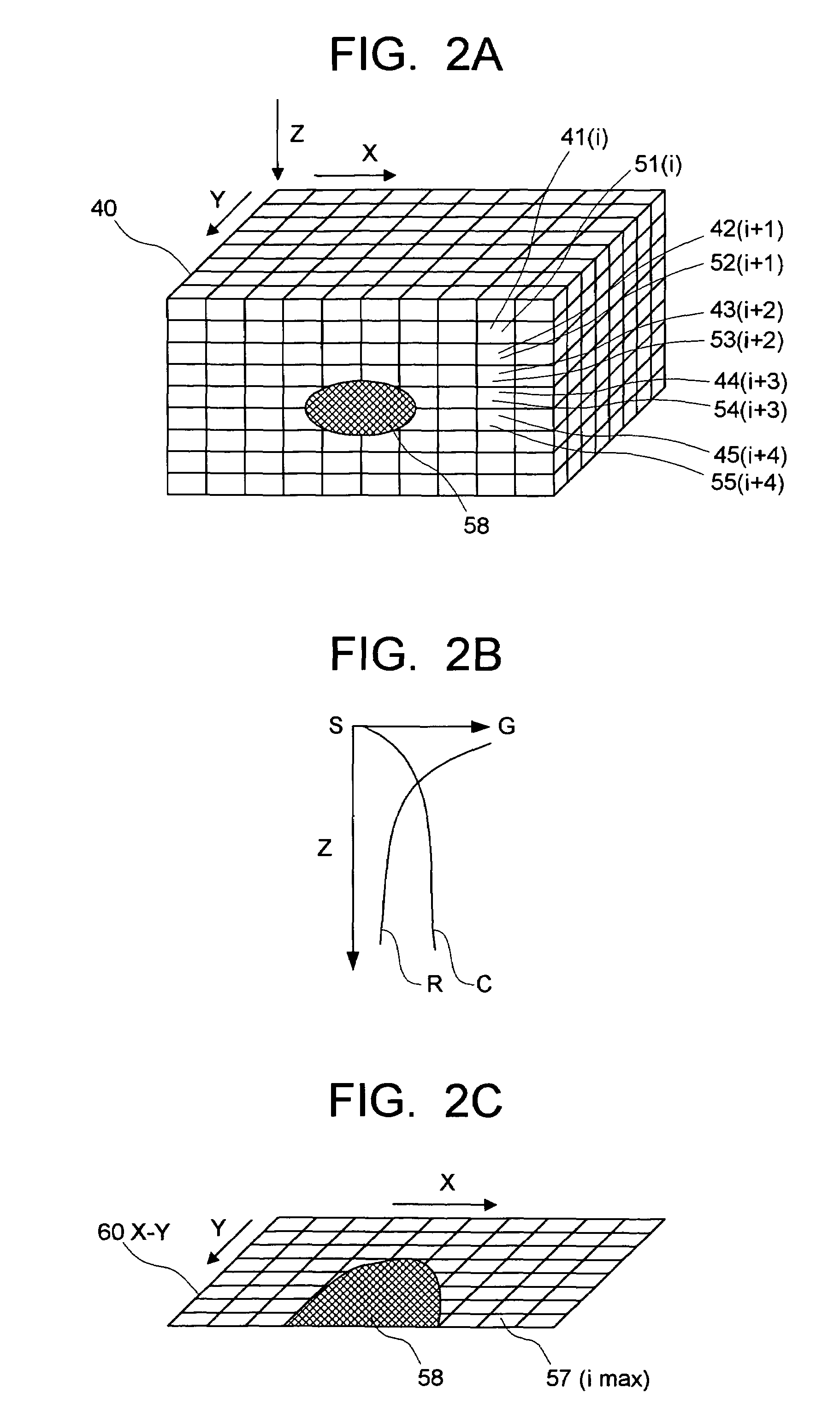
[0028]A three-dimensional ultrasonographic device of this embodiment includes: a signal processing part which generates three-dimensional imaging data corresponding to meshes in a three-dimensional imaging area set in an inspection object; and; a display processing part which has: a function of changing brightness or transparency with which respective meshes set in the three-dimensional area, according to values of the three-dimensional imaging data generated by the signal processing part; and a function of applying masking or image brightness correction to an image of an unnecessary portion of the three-dimensional imaging data, by multiplying the value of the three-dimensional imaging data by a value set according to a three-dimensional coordinate position (X, Y, Z).

[0029]The display processing part includes a two-dimensional image generating part which sees through the three-dimensional imaging data from totally three directions, namely, a direction from a front face as viewed fr...


PUM

PropertyMeasurementUnit
anglesaaaaaaaaaa
anglesaaaaaaaaaa
anglesaaaaaaaaaa

Abstract

This three-dimensional ultrasonographic device is a three-dimensional ultrasonographic device having a matrix sensor 9 composed of a plurality of piezoelectric vibrators which are formed independently and arranged in a matrix, and it generates 3D imaging data based on reflected echoes of an ultrasonic wave obtained from the matrix sensor 9 and processes display images into two-dimensional images. Furthermore, this three-dimensional ultrasonographic imaging device connects a plurality of imaging data that are obtained while the matrix sensor 9 is moved, according to the position of the matrix sensor 9, thereby realizing imaging of a defect 14 for quantitative and intuitive judgment and enabling automatic judgment of the inspection. In addition, in imaging, an area other than an inspection area of the inspection object is masked, which realizes improved image quality.

Description

TECHNICAL FIELD[0001]The present invention relates to a three-dimensional ultrasonographic device that three dimensionally (3D) visualizes a defect, a void, a foreign substance such as an oxide film, and a peeling state of a joint portion in a structure to be inspected, by using ultrasonic waves transmitted / received by a large number of two-dimensionally arranged piezoelectric vibrators.BACKGROUND ART[0002]There has been proposed an ultrasonic inspection device using an ultrasonic transducer composed of a plurality of piezoelectric vibrators that are formed independently from each other and arranged in a matrix (see, for example, Patent document 1). With the conventional ultrasonic inspection device, a layer structure having a plurality of different acoustic characteristics, and a defect, a void, and peeling in an inspection object having a curved surface can be visualized by using ultrasonic waves, but since judgment on the result imaged by the ultrasonic waves relies on eyes, it i...

Claims


Application Information

Patent Timeline
Patent Type & Authority Patents(United States)
IPC IPC(8): G01N29/04G01N29/24G01N29/06G01N29/22G01N29/265G01N29/44
CPCG01N29/043G01N29/06G01N29/0609G01N29/069G01N29/11G01N29/265G01N29/4427G01N2291/0258G01N2291/044G01N2291/106G01N29/04G01N29/22
Inventor KARASAWA, HIROKAZUABE, MOTOHISAITO, YOSHINO
Owner KK TOSHIBA
Why Eureka
Try Eureka