Eureka AIR delivers breakthrough ideas for toughest innovation challenges, trusted by R&D personnel around the world.

Muzzleloading firearm projectile

a projectile and firearm technology, applied in the field of muzzleloading firearm projectiles, can solve problems such as creating interference between the bore of the barrel, and achieve the effect of reasonable alignment of the shank of the bullet and easy loading

Inactive Publication Date: 2008-06-03
SHIERY JEFFREY C
View PDF16 Cites 160 Cited by
  • Summary
  • Abstract
  • Description
  • Claims
  • Application Information

AI Technical Summary

Benefits of technology

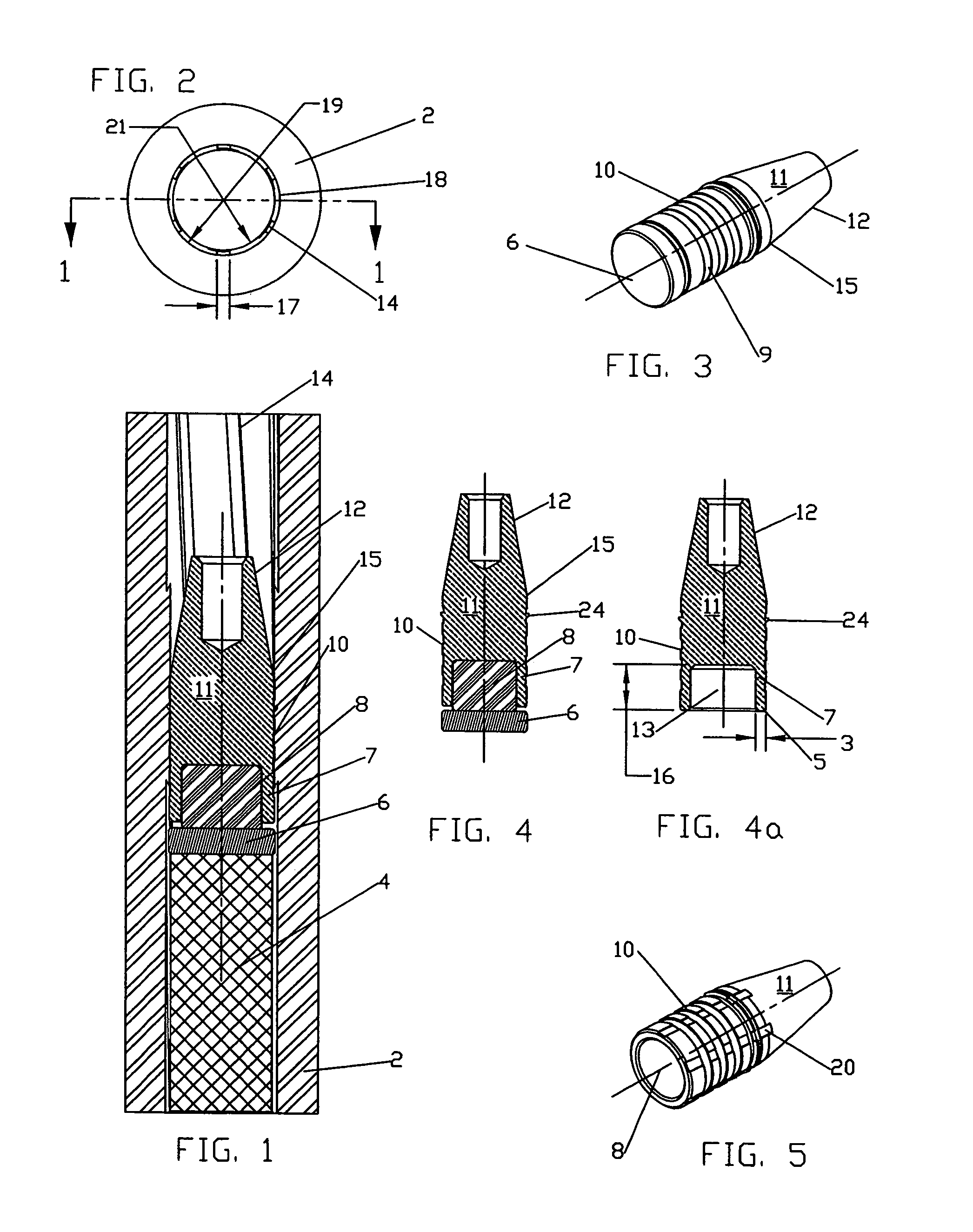
[0011]The objects and purposes of the invention are met by providing a muzzle loading firearm projectile composed of a solid copper multi diameter, hollow base bullet, the rear cavity of which is filled with an expansion plug composed of a low density malleable material used in conjunction with a separate gas pressure seal or check member also composed of a malleable material. The majority of the cylindrical portion of the bullet or shank is slightly smaller in diameter than the bore of the barrel with the exception of a thin web of material located at the transition area between the shank and nose of the bullet that is larger than the bore diameter but smaller than the groove diameter of the firearm barrel. The sub bore portion of the bullet allows for the majority of the bullet to be easily loaded within the barrel and assures reasonable alignment of the shank of the bullet and barrel axis. The ring of material larger than the bore diameter of the barrel deforms to or conforms to the rifling profile of the barrel upon being forced into the barrel to thereby center the nose and top portion of the shank of the projectile with the bore of the firearm. Additionally, the ring also creates interference between the bore of the barrel and the bullet to restrain the projectile in place regardless of firearm positioning.

Problems solved by technology

Additionally, the ring also creates interference between the bore of the barrel and the bullet to restrain the projectile in place regardless of firearm positioning.

Method used


Image

  • Muzzleloading firearm projectile
  • Muzzleloading firearm projectile
  • Muzzleloading firearm projectile

Examples


Embodiment Construction

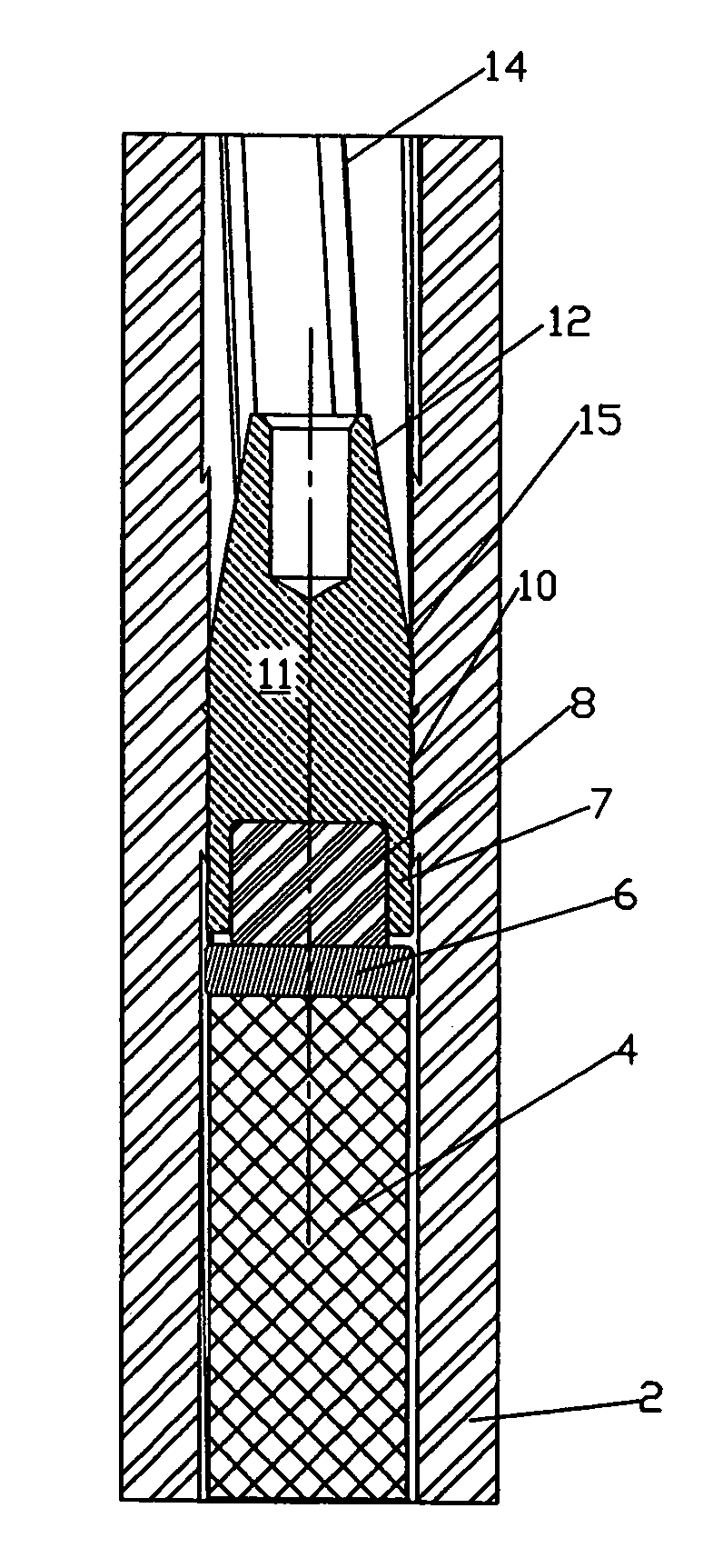
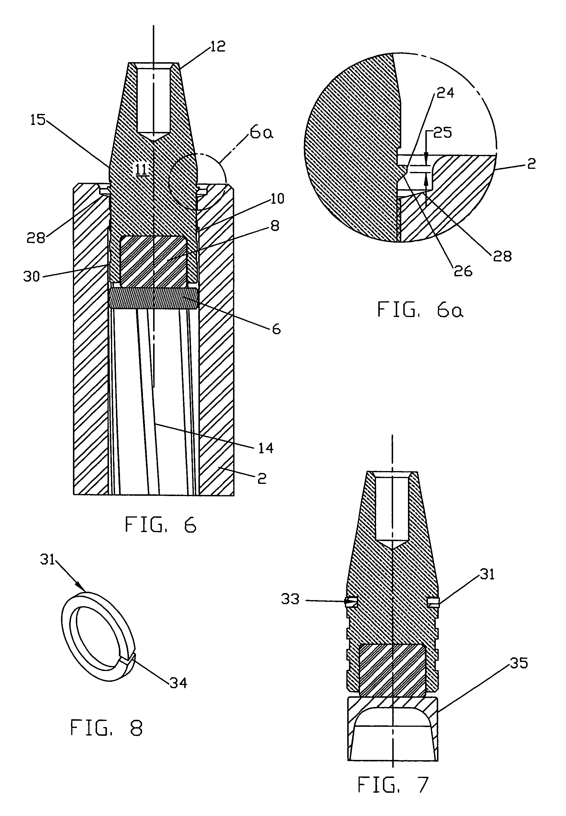
[0026]Referring now to the drawings, there is shown in FIG. 1 a loaded breach assembly composed of a rifled firearm barrel 2, a projectile 15 of this invention, a gas check member 6, and a powder charge 4. The caliber of the firearm barrel 2 may be any one of a number of those popular with the muzzle loading firearm industry. The bore of the barrel is rifled with a series of equally spaced raised spiral grooves 14 and lands 18 that transcend the length of the barrel. The bore diameter is defined as the minor diameter of the rifling grooves 14, is shown in FIG. 2 as number 21. The groove diameter is defined by the rifling lands 18 is defined as number 19. The differential between the rifling bore diameter 21 and the groove diameter 19 is typically between 0.005 and 0.012 inches. The purpose of the rifling is to impart rotary motion to the projectile as it is propelled down the length of the barrel 2 by the propellant gases created from igniting the powder charge 4 creating gyroscopic...


PUM


Abstract

A muzzle loading firearm projectile is disclosed that is composed of a multi diameter, hollow base solid copper bullet, the rear cavity filled with a material of low-density, and a gas pressure seal that separates the bullet from the powder charge. The majority of the bullet shank has a diameter less than the bore diameter of the firearm barrel to allow for ease of loading and alignment of the barrel and bullet axis; a narrow ring of material larger than the barrel bore diameter but less than the groove diameter is located at the junction of the bullet shank and nose profile that centers the bullet in the barrel and positively positions the bullet over the powder charge regardless of orientation of the firearm. The low-density material filling the rear cavity of the bullet acts as an expansion medium when impacted by the rear gas seal during the firing process causing the hollow shank of the bullet to expand and lock into the barrel rifling.

Description

CROSS-REFERENCE TO RELATED APPLICATION[0001]This application is a continuation-in-part of U.S. application Ser. No. 11 / 477,843, filed Jun. 29, 2006, now abandoned.FIELD OF THE INVENTION[0002]This invention relates to firearm projectiles, and, more specifically, to a solid copper or combination polymer / brass full bore projectile for muzzle loading firearms.BACKGROUND OF THE INVENTION[0003]The principles that define usability and contribute to consistent accuracy of muzzle loading firearm projectiles have not changed much since the late 16th century. Firearm and projectile designers have worked continuously to minimize the loading efforts of muzzle loading projectiles while at the same time attempting to develop ideas that would consistently assure an effective gas seal and engagement of the projectile with the rifling of the firearms barrel. If the projectile loading efforts are too high or inconsistent the projectile will not be loaded in contact with the powder charge leading to in...

Claims


Application Information

Patent Timeline
Patent Type & Authority Patents(United States)
IPC IPC(8): F42B14/00
CPCF42B12/34F42B14/02
Inventor SHIERY, JEFFREY C.
Owner SHIERY JEFFREY C
Why Eureka
Eureka Blog
Learn More