Drill cuttings handling apparatus

a technology of cutting cuttings and handling equipment, which is applied in the direction of centrifuges, borehole/well accessories, solid separation, etc., can solve the problems of affecting the time associated with drilling process, requiring a large amount of setup and removal time, etc., and achieves the effects of convenient transportation, convenient system transportation, and easy addition or removal

Active Publication Date: 2008-06-03
TRITON INDS
View PDF5 Cites 27 Cited by
  • Summary
  • Abstract
  • Description
  • Claims
  • Application Information

AI Technical Summary

Benefits of technology

[0007]The present invention provides a portable vacuum and pumping apparatus and system for handling slurries of solids such as the slurry comprised of drill cuttings produced during the drilling of oil and gas wells. The components of the proposed invention can be easily transported and setup on a job location. Because of such portability, ease of assembly, and small footprint, the system it is particularly suitable for use on oil and gas drilling platforms.
[0008]All of the essential components of the drill cuttings handling apparatus may also be arranged and housed as a unit on a transportable skid to minimize the amount of platform deck space utilized by the unit. The transportable skid may be equipped with removable lifting lugs to facilitate its transport to and from the drilling platform or well location.
[0012]The components of the system may be easily transported to and from a well location by trucking or other means. The components may be arranged an mounted on a skid to facilitate transportation of the system. When mounted on a skid, all of the essential components of the apparatus may be contained and incorporated into a single unit. Such a unit may be easily added to or removed from a drilling mud system of a drilling rig assembly. The ease of addition and removal of a unit allows for the ready addition or replacement of a unit in the event of capacity requirements or unit malfunction. Maintenance on the replaced apparatus can then be conducted with little impact on the drilling operation.

Problems solved by technology

These techniques, whether the incorporate conveyors, chutes, suction lines or combinations thereof, typically require elaborate networks of conveyors, hoses, chutes, and tanks that take up valuable rig space.
These systems typically require substantial amounts of time to set up and take down which can have a negative impact on the time associated with the drilling process.

Method used


Image

  • Drill cuttings handling apparatus
  • Drill cuttings handling apparatus
  • Drill cuttings handling apparatus

Examples


Embodiment Construction

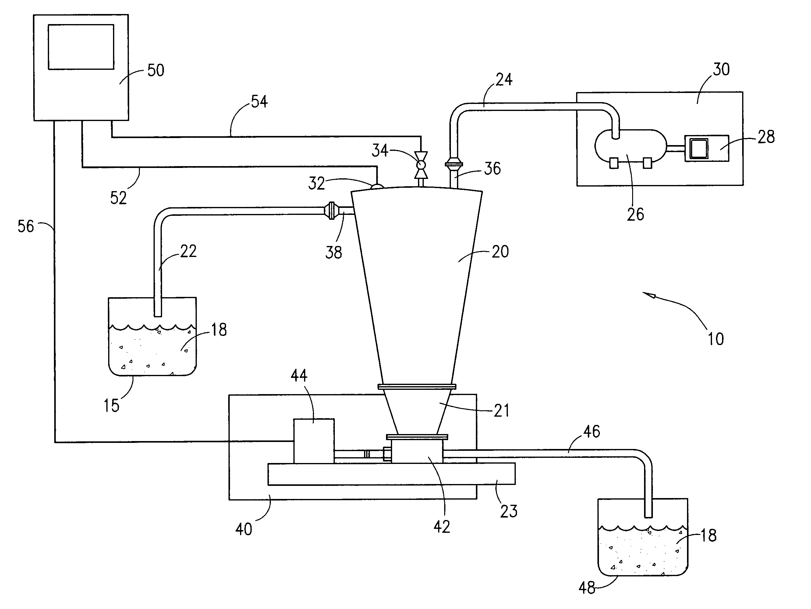
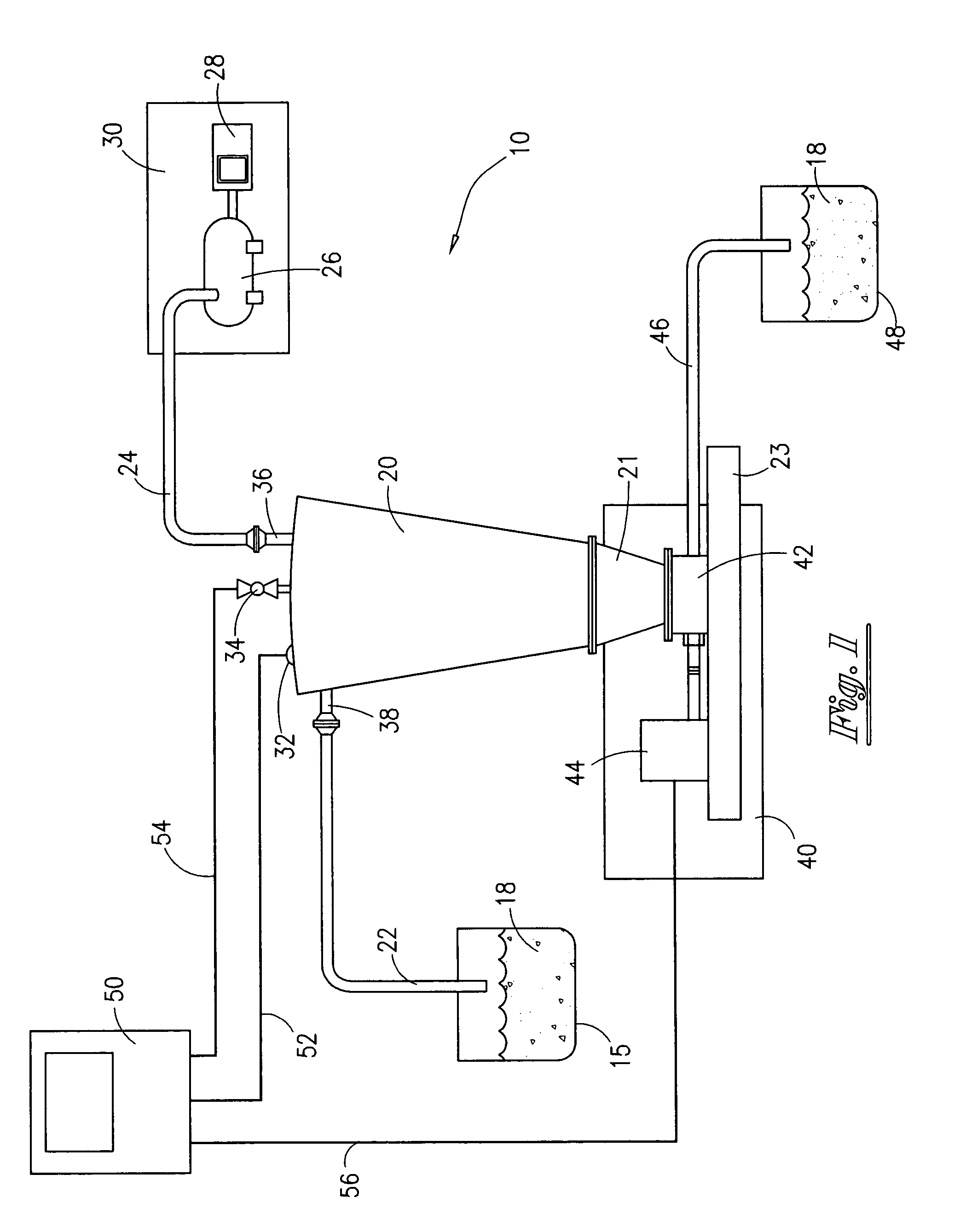
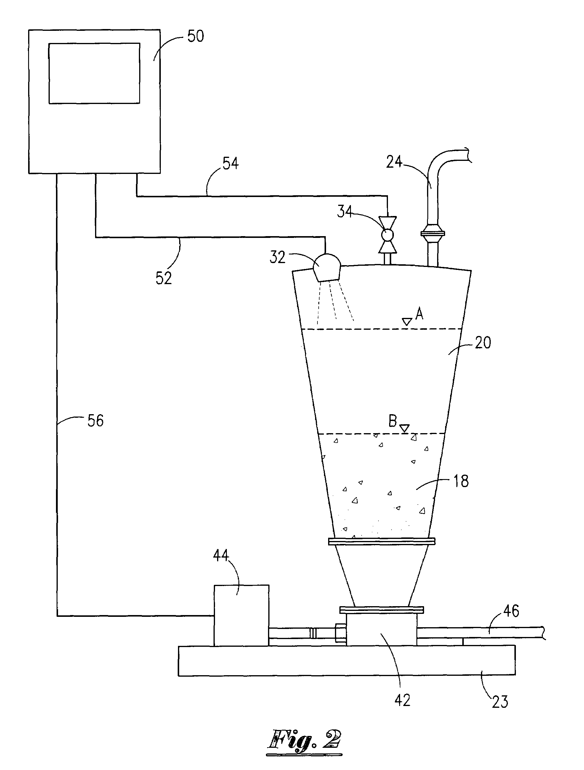
[0015]Referring now to the drawings and more particularly to FIG. 1 there is shown a schematic diagram of the proposed materials handling system (10) to be used as a means for handling slurries of solids such as the slurry comprised of drill cuttings produced during the drilling of oil and gas wells. The system (10) is comprised of a slurry collection tank such as a cyclone cuttings hopper (20), a vacuum system (30), at least one suction line (22), a cuttings discharge system (40), and a control system (50).

[0016]The vacuum system (30) is comprised of a vacuum line (24), a vacuum pump (26), with associated valves and fittings, and a power means (28). It is thought that the power means (28) would be a diesel engine having a horsepower rating sufficient for operating the vacuum pump (26) at a pressure level in the cuttings hopper (20), via vacuum line (24), sufficient to create a desired vacuum or suction level though power means of equivalent power ratings such as electric engines co...


PUM


Abstract

A drill cuttings handling system apparatus for use on an oil and gas drilling rig located on a drilling platform where the platform has drilling equipment that includes a system for circulating drilling mud through the borehole created by the drilling equipment that includes a drill cuttings shaker for removing drill cuttings from the circulating drilling mud and a drill cuttings collection trough. The drill cuttings handling system is comprised of a cyclone cuttings hopper, a vacuum pump, an engine and a solids pump. Conduit is attached to the cyclone cuttings hopper for delivering by vacuum flow a quantity of drill cuttings from the drill cuttings collection trough of the drilling mud system of the drilling rig to the cyclone cuttings hopper. Discharge conduit is connected to the solids pump to dispense drill cuttings from the solids pump to a desired location such as a cuttings box. Control means for detecting the level of cuttings in the system and remotely controlling the flow of cuttings into and out of the hopper by remote control of valves and / or pumps is utilized.

Description

[0001]This application claims priority to U.S. Provisional Application Ser. No. 60 / 633,877 for Drill Cuttings Handling Apparatus filed by Applicant on Dec. 6, 2004, the entire content of which is hereby incorporated by reference.FIELD OF INVENTION[0002]This invention relates to a method and apparatus incorporating a portable vacuum and pumping system to monitor and control the handling of materials such as drill cuttings produced during the drilling of oil and gas wells.BACKGROUND OF INVENTION[0003]In the drilling of oil and gas wells, whether offshore or onshore, rotary drilling techniques require the use of drilling mud circulated through the borehole during the drilling process. Typically, the drilling mud is pumped from a mud holding tank, through mud supply lines, down through the borehole and returned to the surface of the borehole. The circulating drilling mud, as it is returned to the surface of the borehole, is used to carry the drill cuttings produced from the bottom of th...

Claims


Application Information

Patent Timeline
Patent Type & Authority Patents(United States)
IPC IPC(8): E21B21/00
CPCE21B21/066
Inventor JAMES, MICHAEL H.
Owner TRITON INDS
Why Eureka
Try Eureka