Cyclone dust-separating apparatus with discharge electrodes

a technology of discharge electrodes and dust separation apparatus, which is applied in the direction of separation process, filtration separation, auxillary pretreatment, etc., can solve the problems of dust accumulation or spark on the support rod, and achieve the effect of uniform electrical field

Inactive Publication Date: 2008-06-03
SAMSUNG GWANGJU ELECTRONICS CO LTD
View PDF26 Cites 20 Cited by
  • Summary
  • Abstract
  • Description
  • Claims
  • Application Information

AI Technical Summary

Benefits of technology

[0008]An aim of the present disclosure is to provide a cyclone dust-separating apparatus able to distribute the average electric charge uniformly inside the cyclone body and thereby increase dust-separating efficiency.
[0009]Another aim of the present disclosure is to provide a cyclone dust-separating apparatus in which the electrical charge of particles is stable even at a high flow rate.
[0015]Cyclone dust-separating apparatus in the embodiments of the present disclosure described above can charge the dust particles evenly, and thereby distribute the average charge of dust particles evenly, by forming a stable and uniform electrical field throughout the interior of the cyclone body using the cylindrical air exhaust pipe traversing the cyclone.
[0017]Moreover, the cyclone body and the air exhaust pipe may be integrally formed, and by preserving a consistent space between the air exhaust pipe, which functions as a discharge electrode, and the grounding member, a more uniform electrical field can be formed.

Problems solved by technology

Moreover, the electrical charge is unstable at a high flow rate, so a spark can occur or dust can build up on the support rods.

Method used


Image

  • Cyclone dust-separating apparatus with discharge electrodes
  • Cyclone dust-separating apparatus with discharge electrodes
  • Cyclone dust-separating apparatus with discharge electrodes

Examples


first embodiment

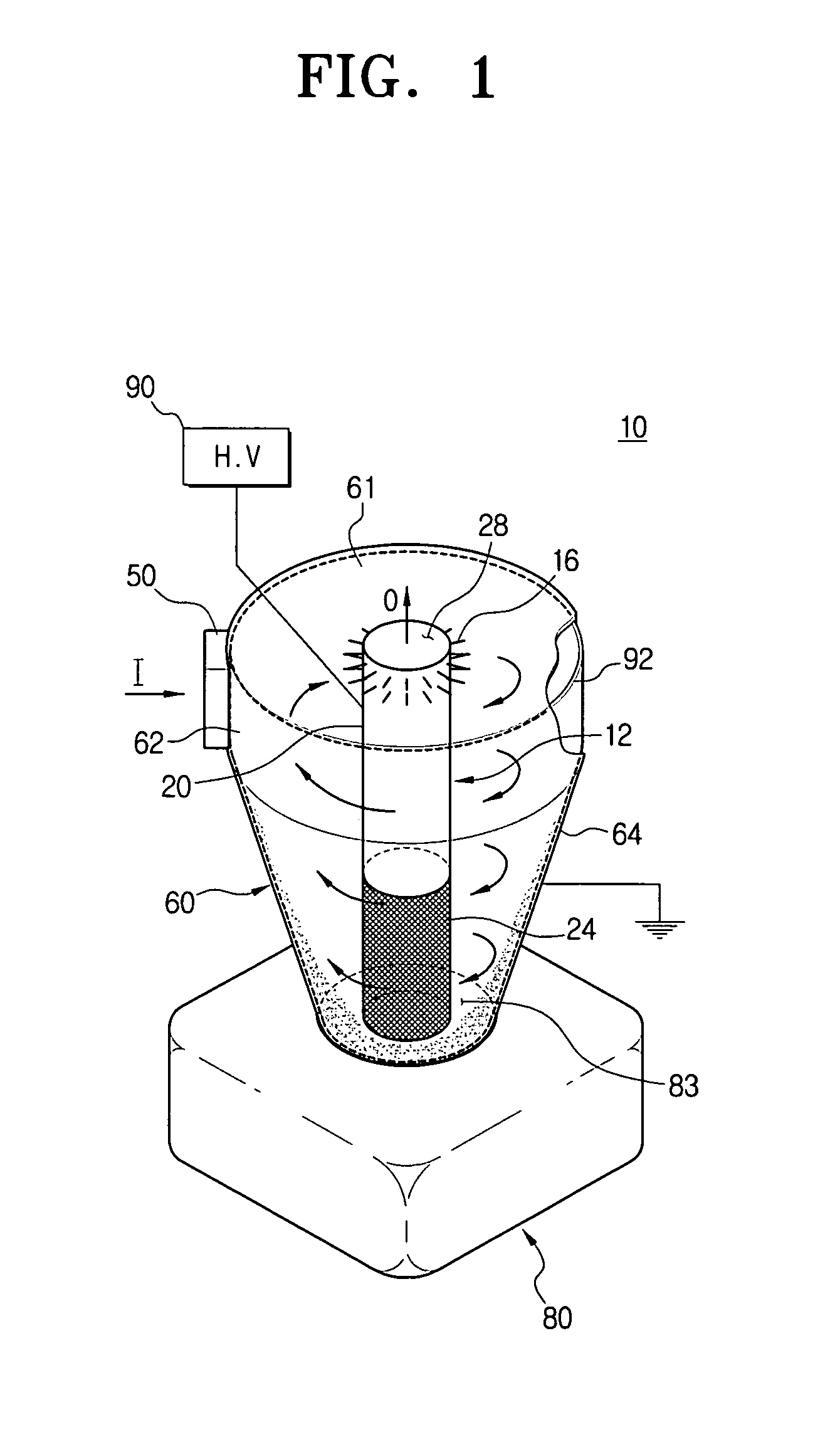
[0022]The preferred embodiments of the present disclosure are explained in greater detail below with reference to the attached drawings. FIG. 1 is a partially incised perspective view schematically showing the cyclone dust-separating apparatus of the present disclosure.

[0023]Referring to FIG. 1, the cyclone dust-separating apparatus 10 comprises an air intake pipe 50, a cyclone body 60, a dust container 80, an air exhaust pipe 12, a plurality of discharge electrode members 16, a grounding member 92, and a high voltage power source 90.

[0024]The air intake pipe 50 is installed on one side of the cyclone body 60, and functions as a passage through which fluid flows into the cyclone body 60 from outside. The air intake pipe 50 may be round, quadrangular, or other shapes, but the embodiments described here have a quadrangular pipe.

[0025]The cyclone body 60 comprises a cylindrical section 62 and a tapering section 64, which tapers downwards in an inverted cone shape, and is an area into w...

second embodiment

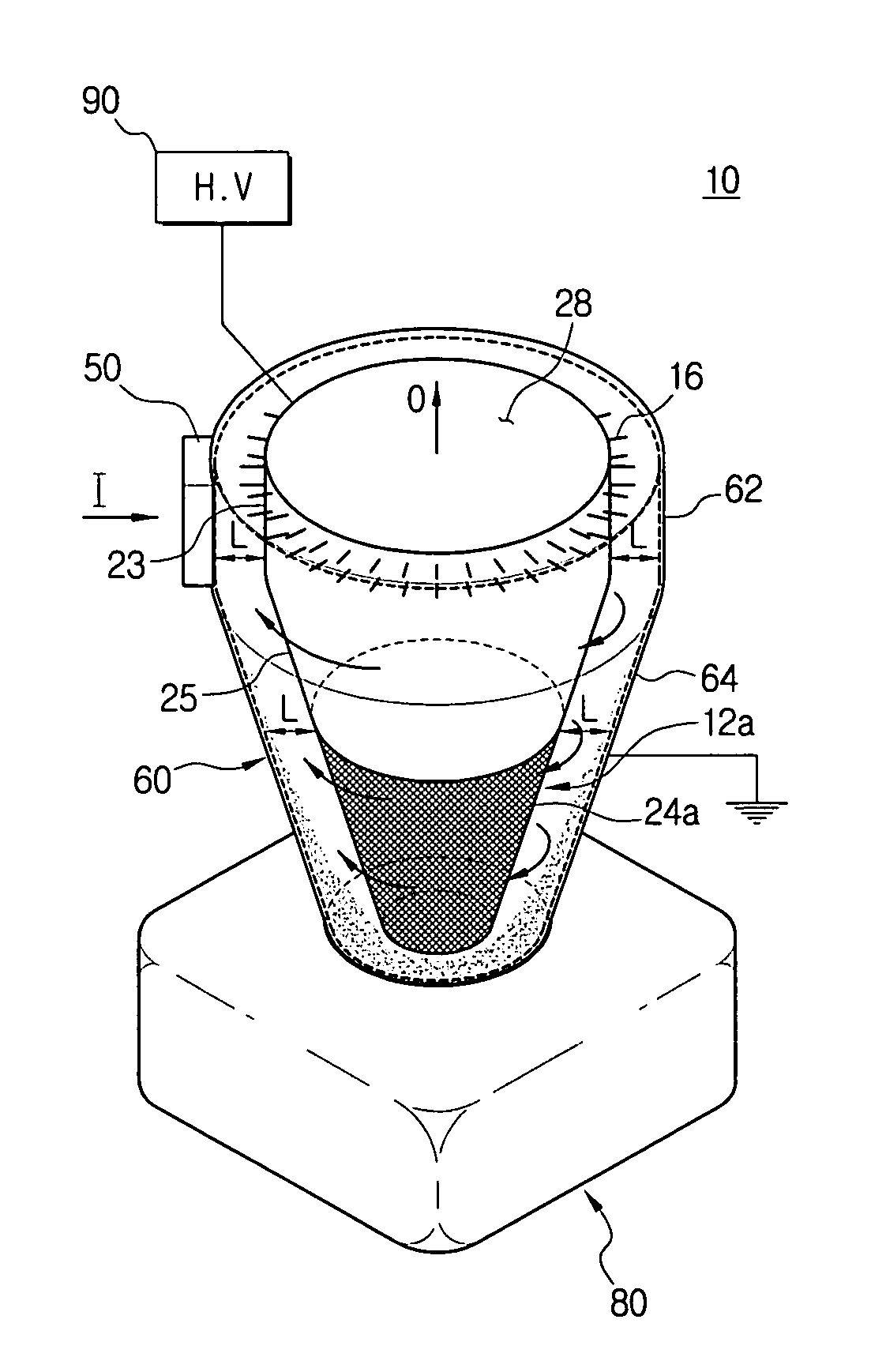
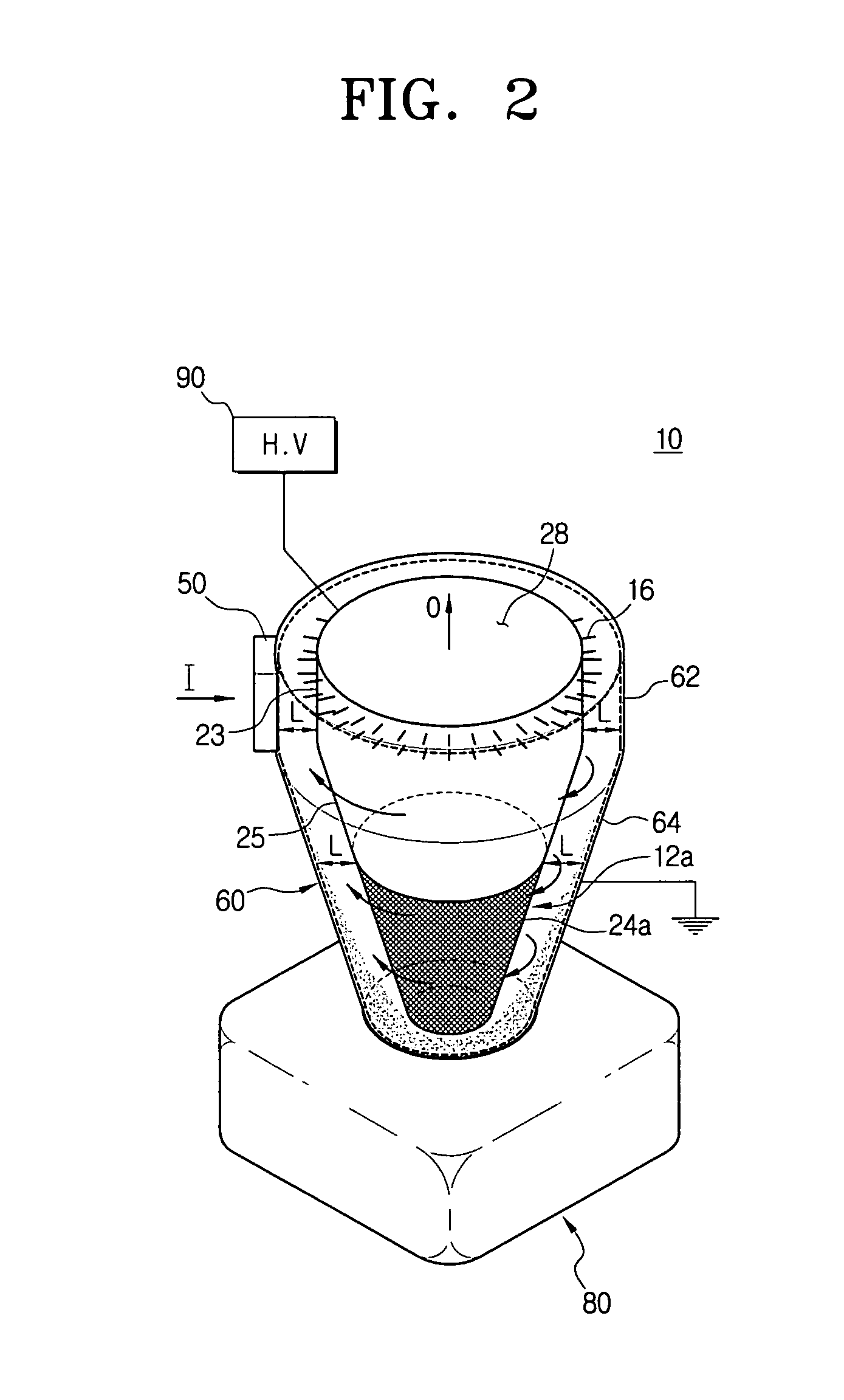
[0033]FIG. 2 is a drawing showing the cyclone dust-separating apparatus of the present disclosure, and differs from FIG. 1 only in the form of the exhaust pipe.

[0034]Referring to FIGS. 1 and 2, the air exhaust pipe 12a has a cylindrical section 23, and a tapering section 25 which decreases in diameter towards the bottom, so the form is consistent with the cyclone body 60. The air exhaust pipe 12a conducts electricity and is connected to the high voltage power source 90, so it functions as a discharge electrode, and the distance L between the outer surface of the air exhaust pipe 12a and the grounding member 92 installed on the inner surface of the cyclone body 60 is uniform, regardless of the position in the cyclone body. In other words, referring to FIG. 2, the distance L between the cylindrical section 23 of the air exhaust pipe 12a, performing the role of a discharging electrode, and the cylindrical section 62 of the cyclone body 60 is equal to the distance L between the sloped s...

third embodiment

[0035]FIG. 3 is a drawing of only the air exhaust pipe 112 of the The remainder of the dust-separating apparatus is identical in form with the embodiment of FIG. 2 described above.

[0036]Referring to FIGS. 2 and 3, the air exhaust pipe 112 in the third embodiment functions as a conductor, and the entire air exhaust pipe 112 is formed of mesh. The high voltage power source 90, referring to FIG. 2, and other components in the dust-separating apparatus are identical to those described for the other embodiments. As a result, air can pass through all parts of the air exhaust pipe 112, but the air exhaust pipe 112 is negatively charged, so dust is driven towards the grounding member 92. The cyclone body 60 comprises a cylindrical section 120 and a tapering section 122, as in the preceding embodiments, and the distance L, in FIG. 2, between the mesh air exhaust pipe 112 functioning as a discharge electrode and the grounding member 92 installed on the inside of the cyclone body 60 is consis...


PUM

PropertyMeasurementUnit
voltageaaaaaaaaaa
areaaaaaaaaaaa
strengthaaaaaaaaaa

Abstract

A cyclone dust-separating apparatus in which the electrical field and particle charge can be uniform and stable. The cyclone dust-separating apparatus comprises: a cyclone body; an air intake pipe, through which air flows from outside into the cyclone body; an air exhaust pipe, through which air flows out of the cyclone body; a grounding member installed on the inside surface of the cyclone body; a plurality of discharge electrode members installed on the air exhaust pipe; and a high voltage power source connected to the air exhaust pipe. The air exhaust pipe conducts electricity, and the discharge electrode members are installed on one or more sides of the air exhaust pipe, are needle-shaped, and protrude from the outer surface of the air exhaust pipe so as to form a uniform and stable electrical field.

Description

CROSS REFERENCE TO RELATED APPLICATIONS[0001]This application claims benefit under 35 U.S.C. § 119(a) of Korean Patent Application No. 2006-03080, filed Jan. 11, 2006, the entire contents of which are incorporated herein by reference.BACKGROUND OF THE INVENTION[0002]1. Field of the Invention[0003]This disclosure relates to a cyclone dust-separating apparatus, and more specifically to a cyclone dust-separating apparatus comprising a plurality of discharge electrodes to raise dust-separating efficiency by improving the form of the electrode that transmits a high voltage.[0004]2. Description of the Prior Art[0005]Cyclone dust-separating apparatus with discharge electrodes are widely used in vacuum cleaners in order to remove dust from the floor of homes and offices, and remove contaminants from gas released from boilers or incinerators.[0006]A conventional cyclone dust-separating apparatus comprises an air intake pipe, which draws air or gas from outside the vacuum cleaner; discharge e...

Claims


Application Information

Patent Timeline
Patent Type & Authority Patents(United States)
IPC IPC(8): B03C3/15
CPCA47L9/1666B03C3/15B03C3/155B04C5/13B04C9/00B03C2201/06B04C2009/001B04C2009/004B03C3/41B03C3/49B03C2201/10A46B7/042A46B2200/302
Inventor KIM, MIN-HAHAN, JUNG-GYUNOH, JANG-KEUN
Owner SAMSUNG GWANGJU ELECTRONICS CO LTD
Why Eureka
Try Eureka