Mercury reduction system and method in combustion flue gas using coal blending

a flue gas and mercury reduction technology, applied in the field of coal combustion, can solve the problems of reducing the amount of mercury in the flue gas, affecting the health of people, and difficult to remove by conventional combustion emission control devices, etc., and achieve the effect of reducing mercury in gas emissions

Active Publication Date: 2008-06-03
GENERAL ELECTRIC CO
View PDF48 Cites 38 Cited by
  • Summary
  • Abstract
  • Description
  • Claims
  • Application Information

AI Technical Summary

Benefits of technology

[0007]In one embodiment, the invention is a method to reduce mercury in gas emissions from the combustion of low rank coal in a combustion system, said method including: combusting coal having a low chlorine content in the combustion system, wherein elemental mercury (Hg0) is released in the flue gas produced by the combustion of the low rank coal; releasing chlorine into the flue gas by combusting a coal having a high chlorine in the combustion system; reacting the elemental mercury and released chlorine in the flue gas to oxidize the mercury; adsorbing at least a portion of the oxidized mercury generated by the combustion of the coal with a solid adsorbent in the flue gas, and collecting the adsorbent with the oxidized mercury in a combustion waste treatment system. Alternatively, oxidized mercury can be removed by wet scrubber.
[0008]In another embodiment, the invention is a method to reduce mercury in gas emissions from the combustion of low rank coal in a combustion system, said method comprising: combusting a Powder River Basin coal (PRB) having a low chlorine content in the combustion system, wherein elemental mercury (Hg0) is released in the flue gas produced by the combustion; releasing chlorine into the flue gas by combusting a bituminous coal having a high chlorine in the combustion system; reacting the elemental mercury and released chlorine in the flue gas to oxidize the mercury and generate mercury chloride (HgCl2); adsorbing at least a portion of the the HgCl2 generated by the combustion of the coal with an adsorbent, and collecting the adsorbent with the HgCl2 in a combustion waste treatment system. Alternatively, oxidized mercury can be removed by wet scrubber.
[0010]In another embodiment, the invention is a method to reduce mercury in gas emissions from the combustion of low rank coal in a combustion system, said method comprising: combusting coal having a low chlorine content in the combustion system, wherein elemental mercury (Hg0) is released in the flue gas produced by the combustion of the low rank coal; releasing chlorine into the flue gas by combusting a coal having a high chlorine in the combustion system; reacting the elemental mercury and released chlorine in the flue gas to oxidize the mercury, and removing at least a portion of the oxidized mercury generated by the combustion of the coal with a water scrubbing device.

Problems solved by technology

The U.S. Environmental Protection Agency (EPA) has identified mercury emissions from power plants as a significant hazard to public health.
However, mercury that remains as elemental mercury tends to remain in the flue gas and is particularly difficult to remove by conventional combustion emission control devices.
The mercury in PRB and lignite coals (collectively “low rank coals”) tends to remain as elemental mercury in the flue gas, and does not readily oxidize or convert to other forms of mercury.
Controlling the emission of mercury in combustion flue gas is complicated because mercury may take different forms.
If the form or speciation of the mercury is not accurately known or changes during emission control treatment, then selecting an effective mercury emission control technology becomes increasingly difficult.

Method used


Image

  • Mercury reduction system and method in combustion flue gas using coal blending
  • Mercury reduction system and method in combustion flue gas using coal blending
  • Mercury reduction system and method in combustion flue gas using coal blending

Examples


Embodiment Construction

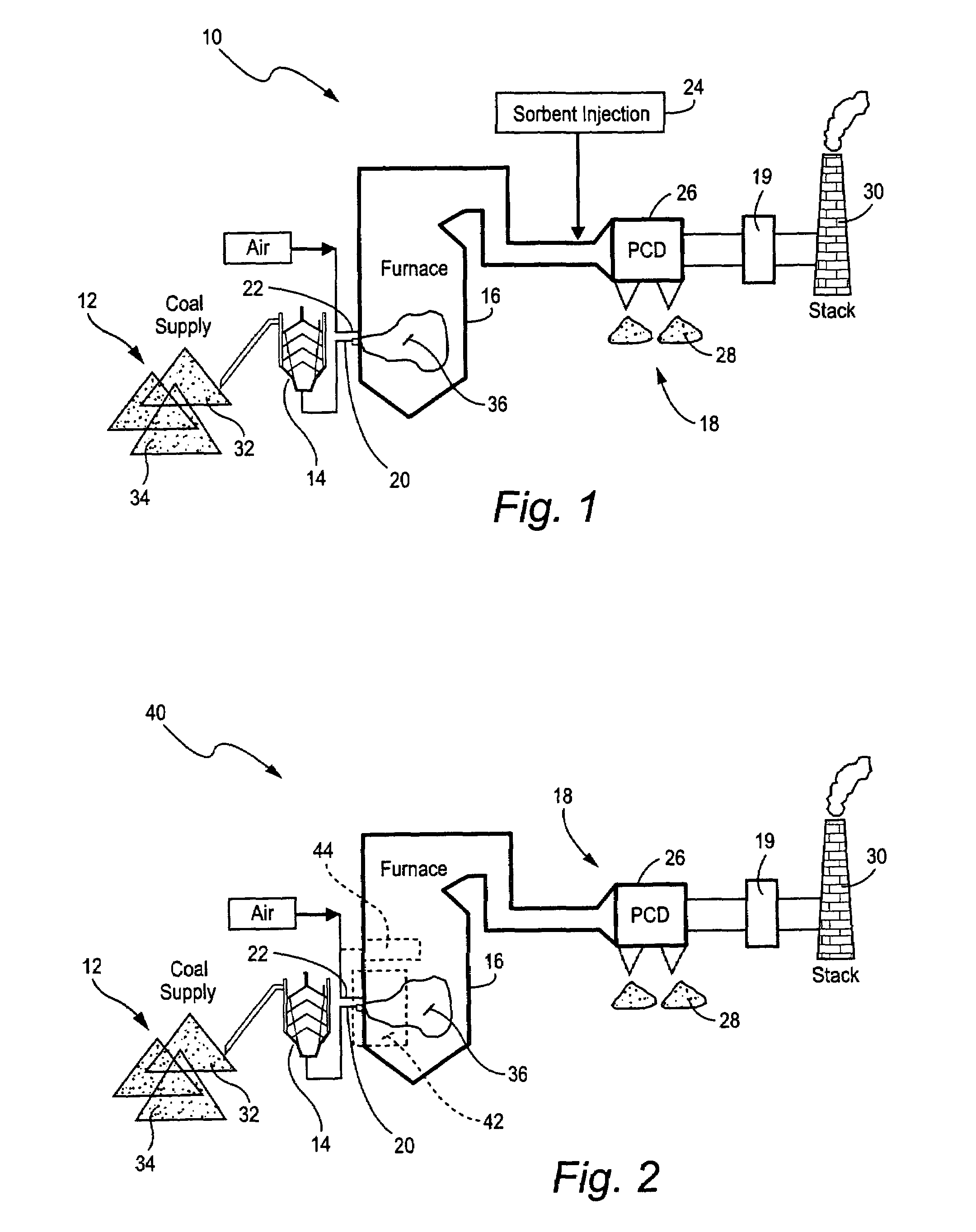
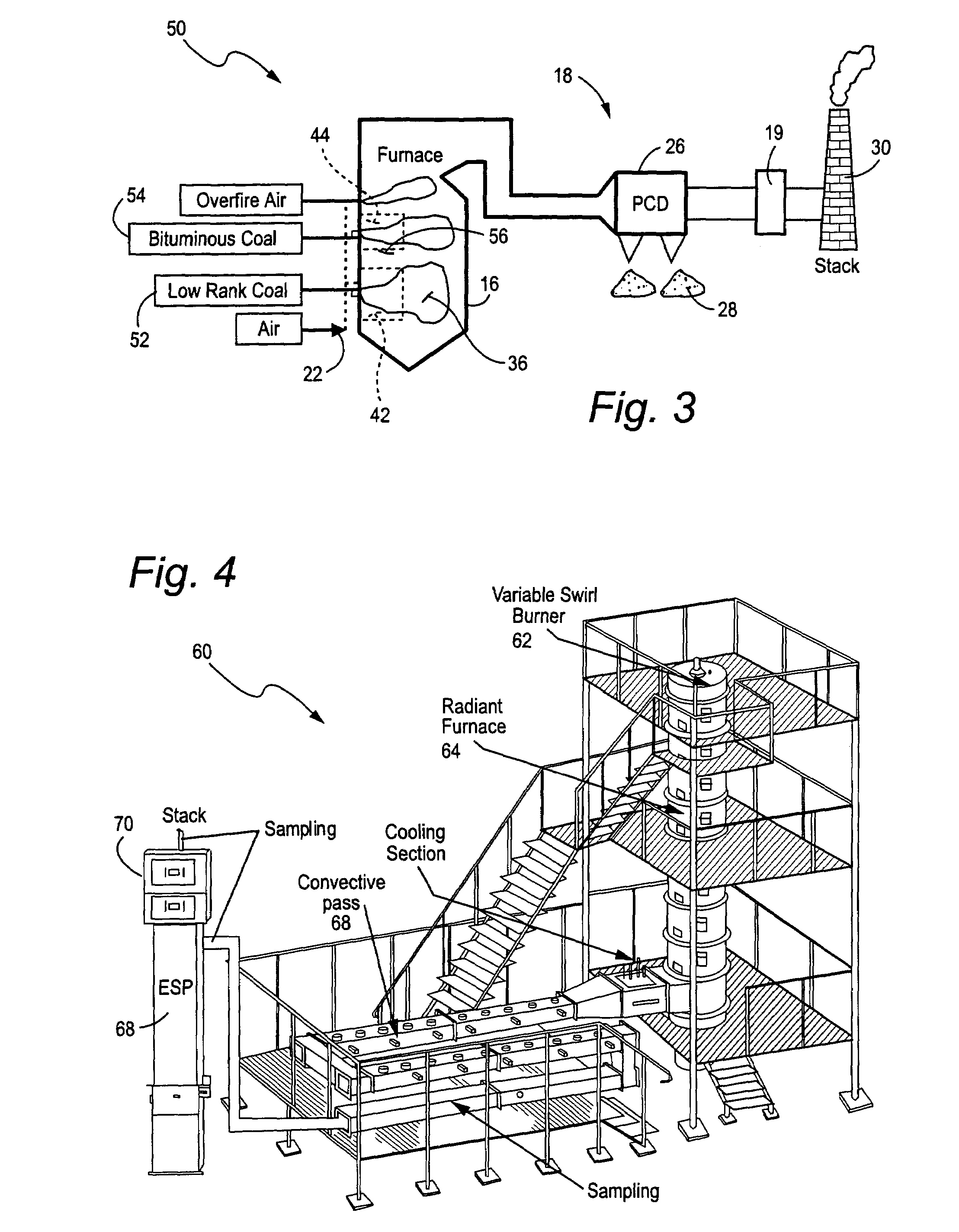
[0017]FIG. 1 shows a coal-fired power plant 10 comprising a supply of various types of coal 12, a coal mixing bin 14, a coal-fired boiler 16, and a combustion waste treatment system 18. The boiler includes a coal fuel injection system 20 and air injectors 22. The combustion waste treatment system includes a sorbent injection system 24, a particulate control device (PCD) 26 with an ash discharge 28, wet scrubber 19, and a stack 30 for flue gas discharge. The PCD captures fly ash and sorbent in the flue gas. The wet scrubber removes SO2 from flue gas.

[0018]The coal supply 12 and mixing bin includes low rank coals 32 and another type of coal 34 having a relatively high chlorine (Cl) content, such as a bituminous coal having an average chlorine content of between 100 to 2000 parts per million (ppm). In contrast Low rank coal 32 typically has a low chlorine content, such as below 100 ppm. Low rank coals are blended with a high chlorine content coal, e.g., a chlorine content above 100 ppm...


PUM

PropertyMeasurementUnit
temperatureaaaaaaaaaa
heightaaaaaaaaaa
diameteraaaaaaaaaa

Abstract

A method to reduce mercury in gas emissions from the combustion of low rank coal in a combustion system including: combusting coal having a low chlorine content in the combustion system, wherein elemental mercury (Hg0) is released in the flue gas produced by the combustion of the low rank coal; releasing chlorine into the flue gas by combusting a coal having a high chlorine in the combustion system; reacting the elemental mercury and released chlorine in the flue gas to oxidize the mercury; adsorbing at least a portion of the oxidized mercury generated by the combustion of the coal with an adsorbent in the flue gas, and collecting the adsorbent with the oxidized mercury in a combustion waste treatment system.

Description

BACKGROUND OF THE INVENTION[0001]This invention relates to the combustion of coal and in particular to the reduction of mercury (Hg) in flue gases generated during coal combustion.[0002]Mercury is a constituent part of coal mineral matter. The emission of mercury from coal-fired power plants is one of major sources of environmental mercury. The U.S. Environmental Protection Agency (EPA) has identified mercury emissions from power plants as a significant hazard to public health. The EPA is considering regulations that would require utility companies operating coal-fired power plants to minimize mercury emissions. Accordingly, there is a need for effective and inexpensive technologies to control mercury emissions from power plants.[0003]Mercury is generally discharged in waste products from coal combustion. Mercury volatizes during coal combustion as elemental mercury (Hg0). A portion of this mercury is oxidized as flue gas cools. It is believed that most oxidized mercury (Hg+2) in fl...

Claims


Application Information

Patent Timeline
Patent Type & Authority Patents(United States)
IPC IPC(8): C01G9/00B01D53/34B01D53/64
CPCB01D53/64F23C1/00F23C6/047B01D2257/602F23C2201/101F23C2201/301
Inventor LISSIANSKI, VITALI VICTORZAMANSKY, VLADIMIR M.MALY, PETER MARTINSEEKER, WILLIAM RANDALL
Owner GENERAL ELECTRIC CO
Why Eureka
Try Eureka