Power cable for direct electric heating system

a technology of direct electric heating and power cables, which is applied in the direction of power cables, cables, insulated conductors, etc., can solve the problems of affecting the flow of electricity in the line, affecting the safety of the environment, and requiring high-speed transmission

Active Publication Date: 2008-06-03
NEXANS
View PDF2 Cites 26 Cited by
  • Summary
  • Abstract
  • Description
  • Claims
  • Application Information

AI Technical Summary

Problems solved by technology

This is a problem when the pipes are cooled in seawater, particularly during a shutdown of production, which causes the flow in the line to be impeded or even blocked due to the formation of hydrates or wax plugs.
However, this method has considerable operational costs and presents a risk to the environment should a leakage occur.
The first alternative is found to be rather inefficient, and the second very expensive.
As the pipeline expands and contracts during operation, the cable is generally subject to stretching and sliding forces against the seabed.
These problems are aggravated, if the pipeline spans valleys between reefs or boulders on the seabed.
In this case, an alternating current causes excessive electric losses if a metal armoring is applied to the cable.
It is difficult to achieve good dynamic properties with a cross section that comprises two (large) conductors, as bending properties become very dependent on the bending plane.
For improving the properties in this respect, it would be possible to design and use a three-core dynamic cable, and consider one core as spare, but this solution results in dimensions, weight and cost being far from optimized.

Method used


Image

  • Power cable for direct electric heating system
  • Power cable for direct electric heating system
  • Power cable for direct electric heating system

Examples


Embodiment Construction

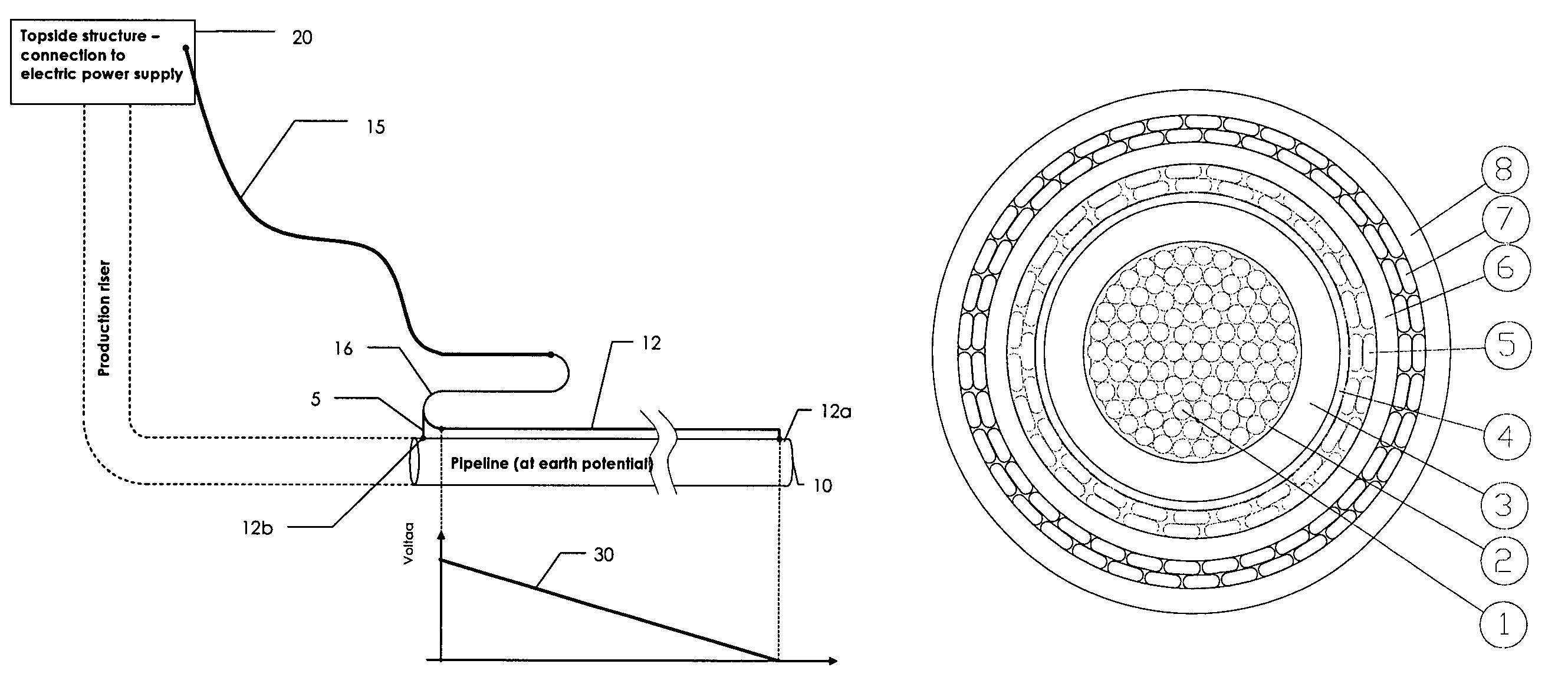
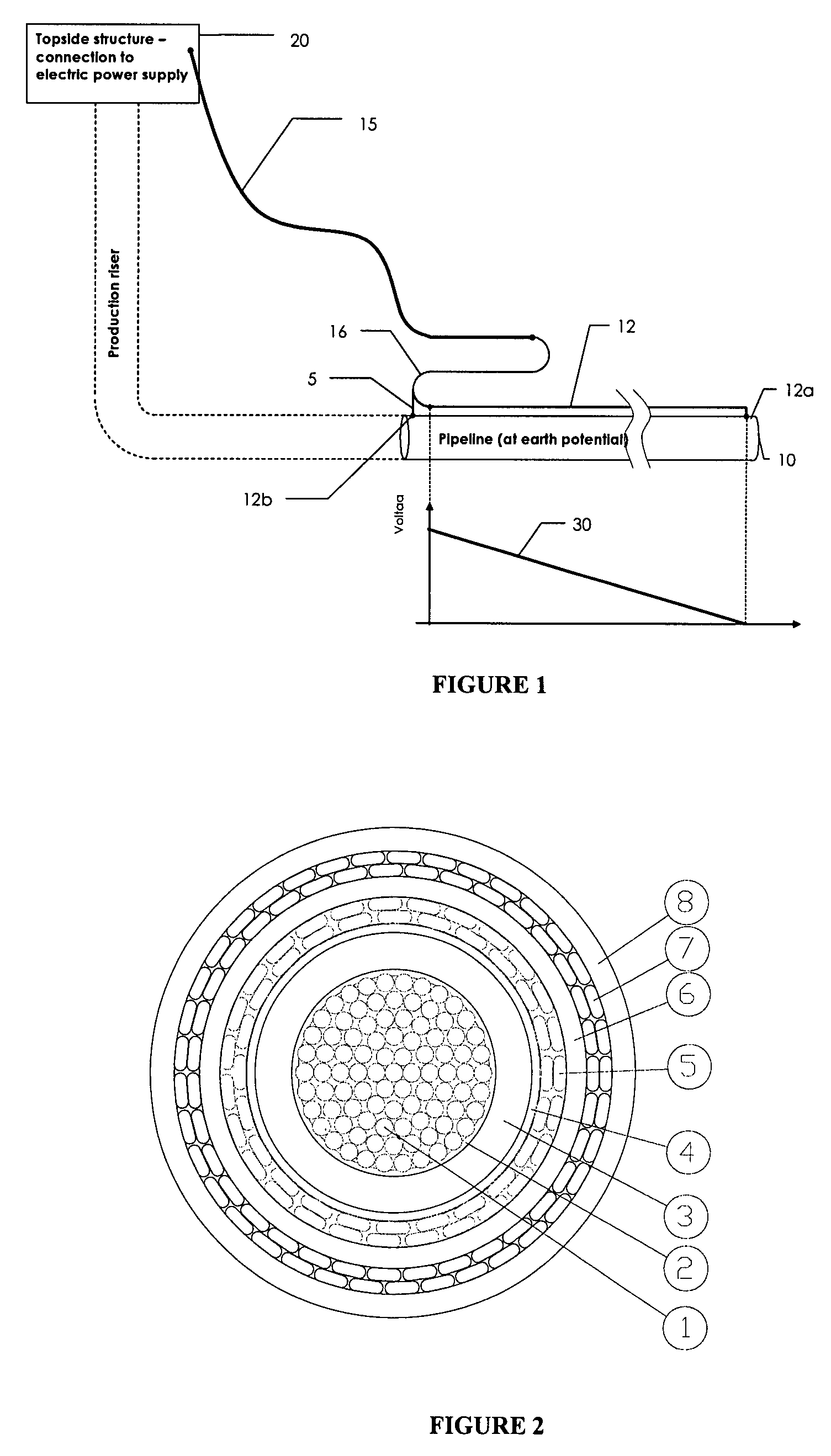
[0033]FIG. 1 illustrates a pipeline 10 with a direct electric heating system comprising an electric power cable and a terminal assembly according to the present invention.

[0034]An electric power supply unit arranged on a topside structure 20 comprised by the total plant or platform concerned. From the power supply unit there is a two-conductor supply cable or riser cable 15 extended down to the subsea installation concerned, where there is provided an armored feeder cable 16. The lower end of cable 16 is at one side connected to the near end 12b of the piggyback cable 12, and on the other side (the other conductor) is connected as shown at 12a to the far end of pipeline 10.

[0035]The pipeline 10 has an outer thermal insulation ensuring that crude oil or condensate coming from the well template has a sufficiently low viscosity until it reaches the platform 20. If the pipeline flow is stopped, formation of hydrate plugs and wax deposits occur which can block the pipeline when fluid tra...


PUM

PropertyMeasurementUnit
voltagesaaaaaaaaaa
voltageaaaaaaaaaa
areaaaaaaaaaaa

Abstract

Electric power cable used as a riser (15) and / or feeder cable (16) in a Direct Electric Heating system for oil or condensate pipelines (10), comprising at least two conductors (1, 5) and insulation layers (3, 6). An outer concentric conductor (5) is connected to a near end of the pipeline, and a central conductor (1) is connected via a piggyback cable (12) to a far end of the pipeline, to provide power for the heating. Another aspect is a terminal assembly adapted to providing an electric connection of the electric power cable with the pipeline (10), where a cone (41) is adapted to squeeze the concentric conductor (5) against a concentric conductor adapter (40).

Description

RELATED APPLICATION[0001]The present invention is related to and claims the benefit of priority from Norwegian Patent Application No. 2006 1613, filed on Apr. 10, 2006, the entirety of which is incorporated herein by reference.BACKGROUND OF THE INVENTION[0002]1. Field of the Invention[0003]The present invention generally relates to the field of subsea electric power cables. More specifically, it relates to a coaxial dynamic riser and feeder cable for direct electric heating (DEH) of an oil or condensate pipeline and a termination of the coaxial feeder cable to the pipeline.[0004]2. Description of the Related Art[0005]The temperature of the oil or condensate in the underground reservoirs is typically about 90° C. The oil or condensate well stream contains several liquid substances that freeze when the temperature drops. This is a problem when the pipes are cooled in seawater, particularly during a shutdown of production, which causes the flow in the line to be impeded or even blocked...

Claims


Application Information

Patent Timeline
Patent Type & Authority Patents(United States)
IPC IPC(8): H01B7/18F16L53/37
CPCF16L53/007H01B7/14H01R4/643H01R4/5016H01R9/0524F16L53/37F16L53/00H01B9/04
Inventor BREMNES, JARLE JANSENNYGARD, OLE KRISTEN
Owner NEXANS
Why Eureka
Try Eureka