Capacitive pressure sensor

a capacitive pressure sensor and capacitive technology, applied in the direction of fluid pressure measurement, variable capacitors, instruments, etc., can solve the problems of capacitive pressure sensor sensitivity likely to be degraded, and achieve the effects of improving sensor sensitivity and air tightness, high adhesiveness, and improving air tightness

Inactive Publication Date: 2008-06-03
ALPS ALPINE CO LTD
View PDF12 Cites 19 Cited by
  • Summary
  • Abstract
  • Description
  • Claims
  • Application Information

AI Technical Summary

Benefits of technology

[0009]In one embodiment, the fixed electrode and the projection are integrally formed. A separate member is not interposed between the fixed electrode and the projection. In this embodiment, the projection is separated from a pressure-sensitive diaphragm. Accordingly, it is possible to minimize a parasitic capacitance other than capacitance between the pressure-sensitive diaphragm and the fixed electrode. Sensitivity of the capacitive pressure sensor can be improved. In addition, since a lead electrode does not need to be formed in the bonded region of the glass substrate and the second silicon substrate, airtightness inside the cavity can be improved.
[0012]In one embodiment, interfaces between the glass substrate and the first and second silicon substrates may have Si—Si bonding or Si—O bonding. In this embodiment, the interface between the glass substrate and the silicon substrate has the Si—Si bonding or Si—O bonding, and thus the silicon and the glass are tightly bonded to each other. Thus, the interface therebetween shows high adhesiveness, and airtightness of the cavity is improved.
[0013]In one embodiment, the capacitive pressure sensor includes a glass substrate that has a pair of main surfaces facing each other. A first silicon substrate has a fixed electrode passing through the glass substrate to be exposed at one main surface and a projection passing through the glass substrate to be exposed at the one main surface. A second silicon substrate is bonded to the one main surface of the glass substrate and is disposed to face the fixed electrode so as to form a cavity between the second silicon substrate and the fixed electrode. Therefore, it is possible to improve sensor sensitivity and airtightness in the cavity between the diaphragm and the fixed electrode.

Problems solved by technology

However, in this structure, since the lead electrode 5 is located near the diaphragm 4a, parasitic capacitance other than capacitance between the diaphragm 4a and the fixed electrode 3 is large, and thus sensitivity of the capacitive pressure sensor is likely to be degraded.

Method used


Image

  • Capacitive pressure sensor
  • Capacitive pressure sensor
  • Capacitive pressure sensor

Examples


Embodiment Construction

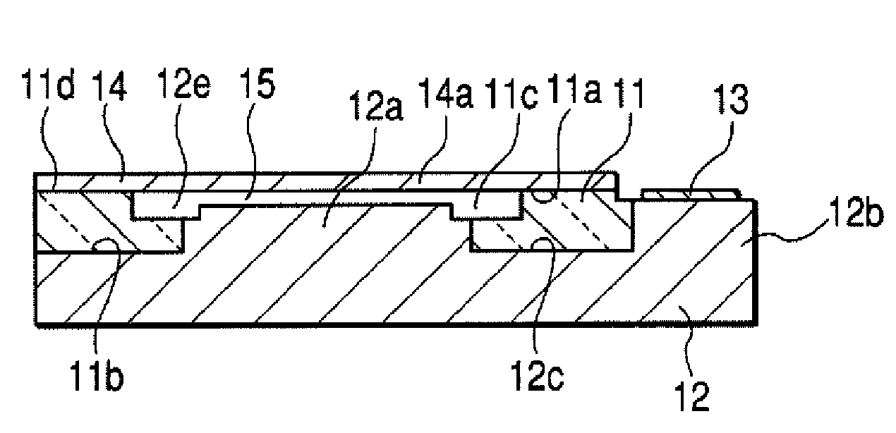
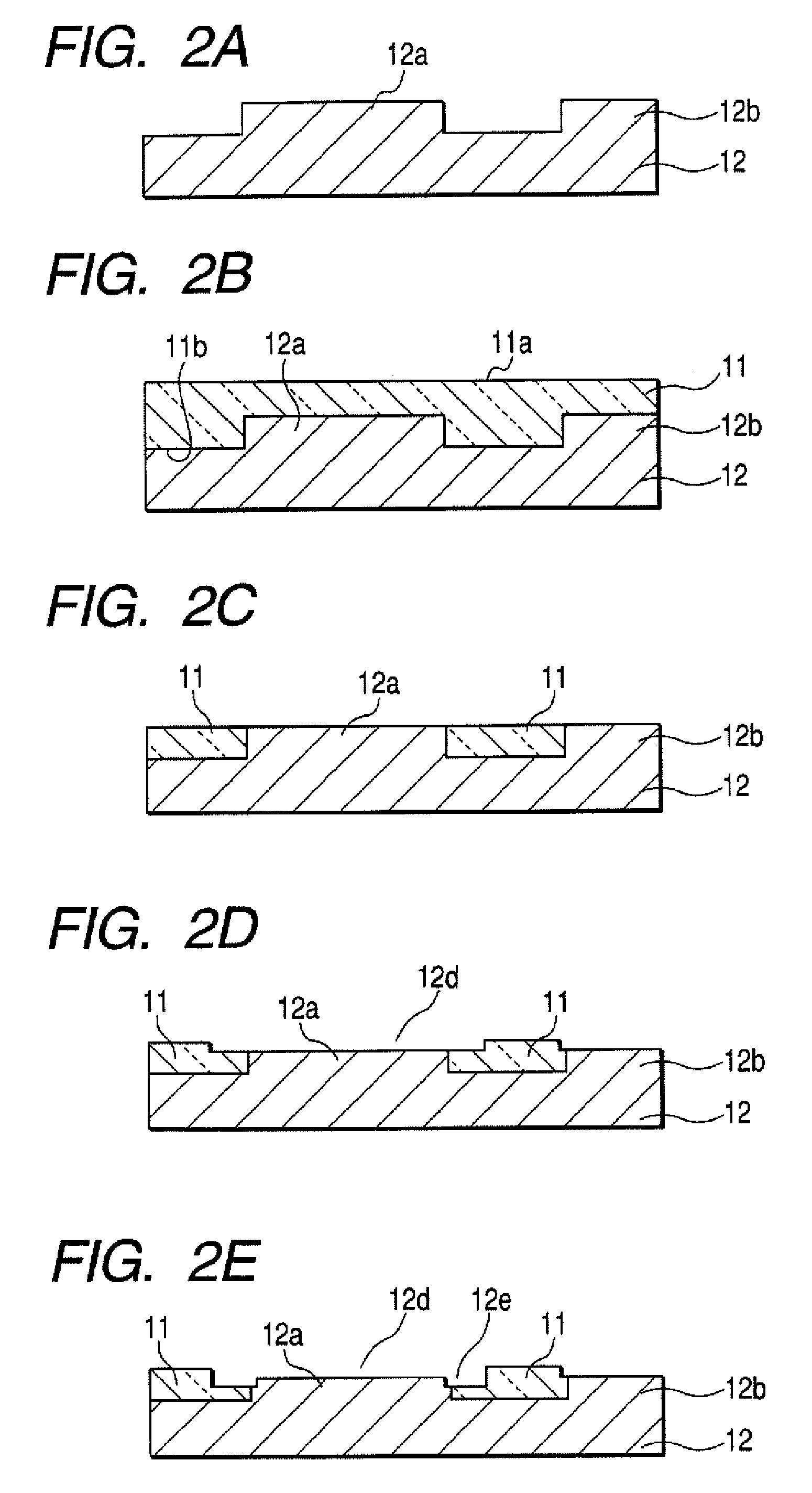
[0019]One embodiment will now be described with reference to the accompanying drawings. FIGS. 1A and 1B are views showing a capacitive pressure sensor according to one embodiment. FIG. 1A is a cross-sectional view, and FIG. 1B is a plan view.

[0020]Reference numeral 11 indicates a glass substrate. The glass substrate 11 includes a pair of main surfaces 11a and 11b. A first silicon substrate 12 is bonded to the main surface 11b of the glass substrate 11. The first silicon substrate 12 has a fixed electrode 12a and a projection 12b. The fixed electrode 12a and the projection 12b pass through the glass substrate 11 to be exposed at the main surface 11a.

[0021]A concave portion 11c is formed at the main surface 11a of the glass substrate 11 so as to form a cavity. The depth of the concave portion 11c is set so as to maintain a predetermined cavity gap in such a range that the exposed fixed electrode 12a inside the cavity is in contact with a pressure-sensitive diaphragm described below. ...


PUM


Abstract

A capacitive pressure sensor is provided. The capacitive pressure sensor includes a glass substrate that has a pair of surfaces facing each other. A first silicon substrate has a fixed electrode passing through the glass substrate to be exposed at one surface and a projection passing through the glass substrate to be exposed at the one surface. A second silicon substrate is bonded to the one surface of the glass substrate and is disposed to face the fixed electrode so as to form a cavity between the second silicon substrate and the fixed electrode.

Description

[0001]This patent document claims the benefit of Japanese Patent Application No. 2005-315586 filed on Oct. 31, 2005, which is hereby incorporated by reference.BACKGROUND[0002]1. Field[0003]The present embodiments relate to a capacitive pressure sensor and a method of manufacturing the same.[0004]2. Related Art[0005]Generally, a capacitive pressure sensor includes a substrate that has a pressure-sensitive diaphragm as a movable electrode and a substrate that has a fixed electrode. The substrates are bonded to each other at a predetermined gap between the pressure-sensitive diaphragm and the fixed electrode. In the capacitive pressure sensor, if pressure is applied to the pressure-sensitive diaphragm, the pressure-sensitive diaphragm is deformed, and the gap between the pressure-sensitive diaphragm and the fixed electrode changes accordingly. The change of the gap causes a change in capacitance between the pressure-sensitive diaphragm and the fixed electrode. Thus, a change in pressur...

Claims


Application Information

Patent Timeline
Patent Type & Authority Patents(United States)
IPC IPC(8): H01G7/00
CPCG01L9/0073
Inventor KIKUIRI, KATSUYASATO, KIYOSHIFUKUDA, TETSUYANAKAMURA, YOSHINOBUKOBAYASHI, HIROYUKI
Owner ALPS ALPINE CO LTD
Why Eureka
Try Eureka