Continuous steam generator and method for operating said continuous steam generator

a continuous steam generator and steam technology, applied in steam generation heating methods, steam generation using hot heat carriers, water circulation, etc., can solve the problem that the maximum possible temperature distortion can be limited accordingly, and achieve high flow stability and high operating safety

Inactive Publication Date: 2008-06-10
SIEMENS AG
View PDF15 Cites 10 Cited by
  • Summary
  • Abstract
  • Description
  • Claims
  • Application Information

AI Technical Summary

Benefits of technology

[0016]Such an arrangement of the segments in the heating-gas channel largely retains the advantage of a pure counterflow circuit in transferring the heat of the waste gas effectively to the flow medium and at the same time achieves a high degree of intrinsic protection against harmful temperature differences at the flow-medium-side outlet.
[0020]The advantages achieved by means of the invention are in particular that the overall temperature interval achievable in the evaporation of the flow medium between saturated-steam temperature of the flow medium and heating-gas temperature at the outlet point is comparatively narrowly delimited by means of the positioning now provided, adapted to the temperature profile of the heating gas in the gas duct, of the flow-medium-side outlet of the evaporator throughflow heating surface, so that only small temperature differences at the outlet side are possible, independently of the flow conditions. This enables adequate equalization of the temperatures of the flow medium to be ensured in every operating state. Also, the evaporator throughflow heating surface is more stable in terms of flow than a pure counterflow circuit as a result of the appropriate positioning of the flow-medium-side inlet of the evaporator throughflow heating surface at the gas-side inlet of the evaporator throughflow heating surface. Consequently, a particularly high flow stability and a particularly high operating safety are ensured for the steam generator. In addition, however, it is also ensured that the possible outlet temperatures are limited in their absolute level so that they remain safely below the admissible threshold temperatures predetermined by the material properties.

Problems solved by technology

Through appropriate coordination of these two threshold temperatures which delimit any possible temperature interval that there may be, the maximum possible temperature distortions can consequently also be limited appropriately.

Method used


Image

  • Continuous steam generator and method for operating said continuous steam generator
  • Continuous steam generator and method for operating said continuous steam generator

Examples


Embodiment Construction

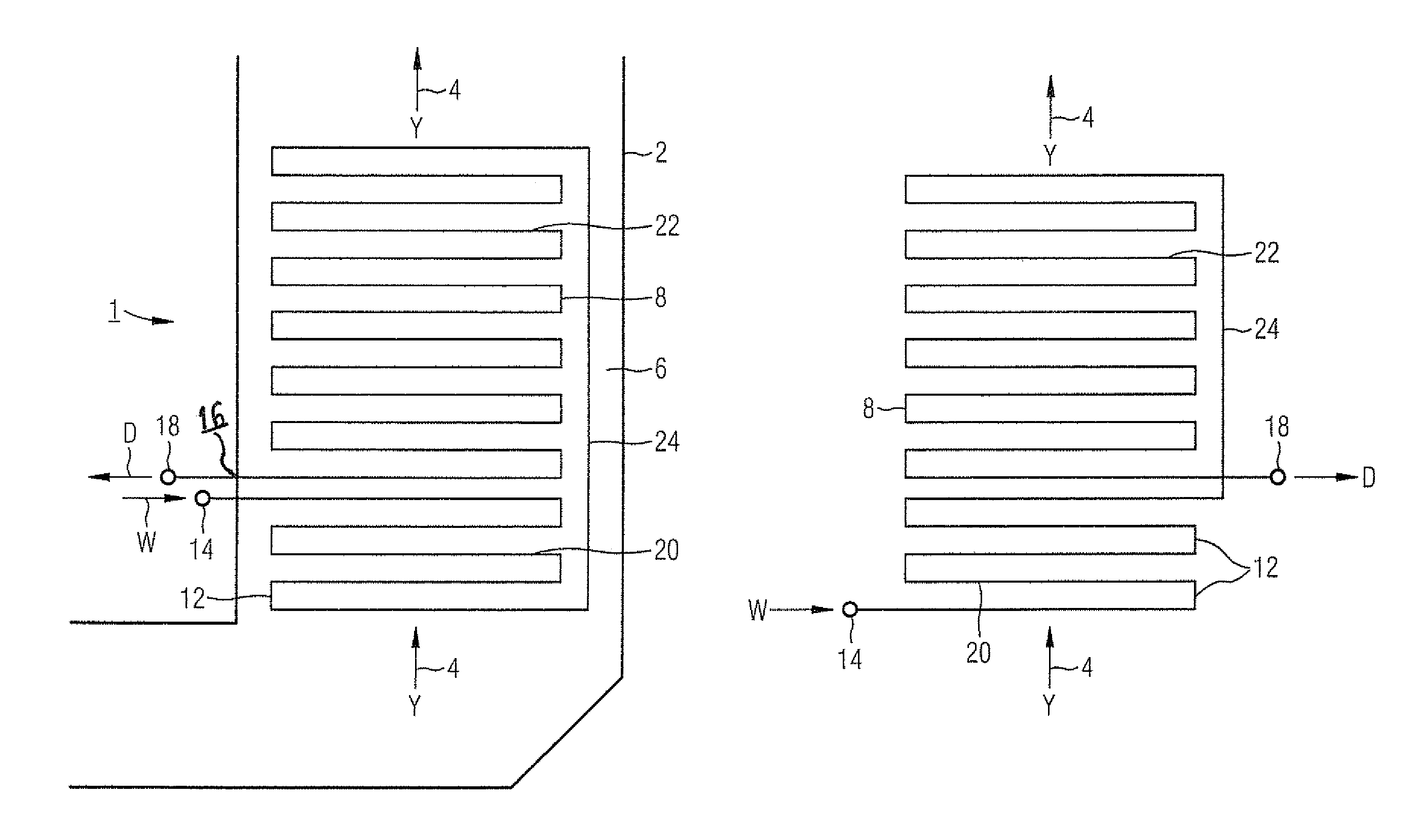
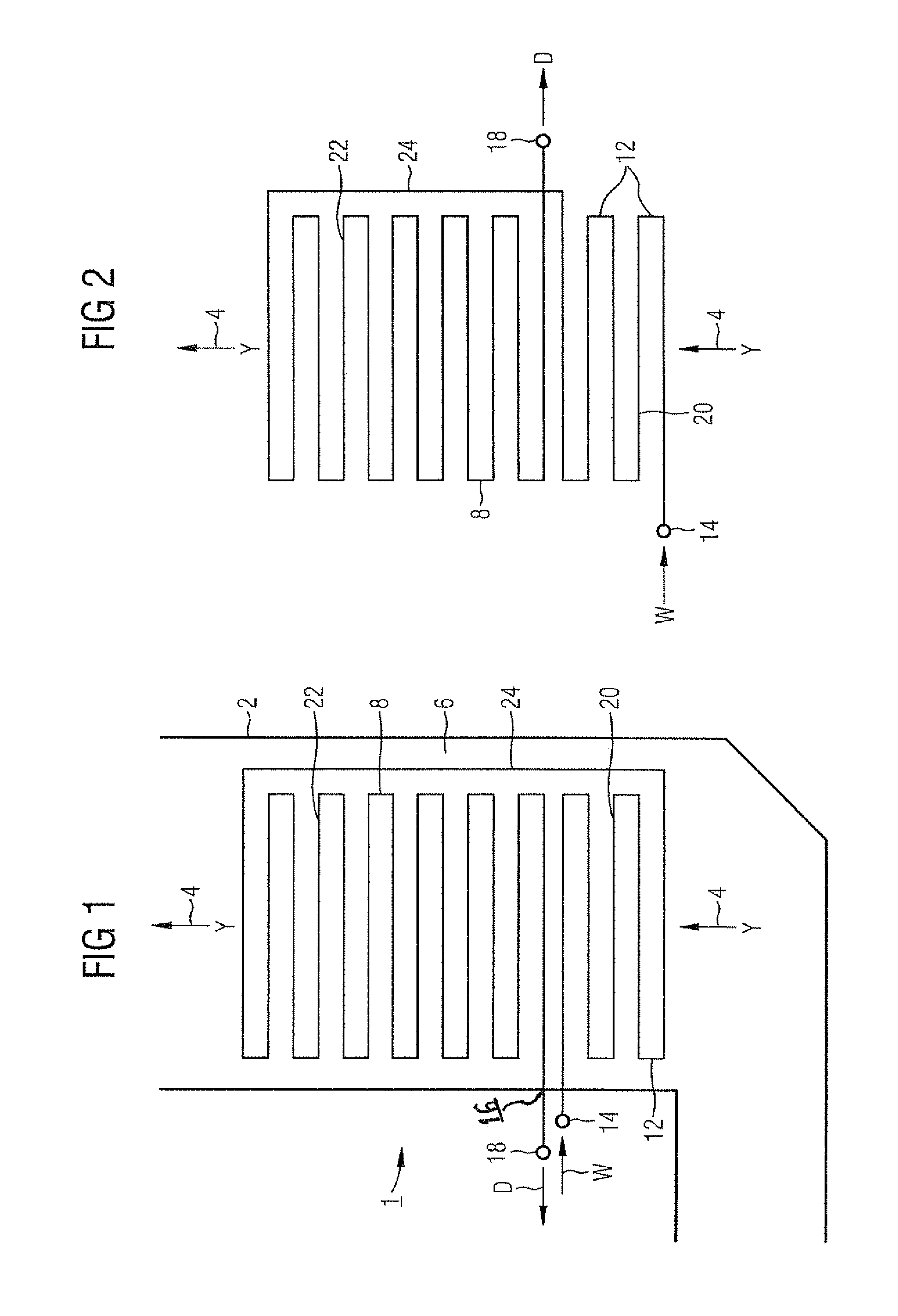
[0024]The same reference symbols are used to label the same parts in the two Figures.

[0025]The continuous-flow steam generator 1 according to FIG. 1 is connected in the manner of a waste-heat steam generator on the waste-gas side downstream of a gas turbine, not shown in detail. The continuous-flow steam generator 1 has an enclosing wall 2 which forms a gas duct 6, through which heating gas can flow in a nearly vertical direction y indicated by the arrows 4, for the waste gas out of the gas turbine. A number of heating surfaces laid out according to the continuous-flow principle, in particular an evaporator throughflow heating surface 8, are disposed in the gas duct 6. In the exemplary embodiment according to FIG. 1, only the evaporator throughflow heating surface 8 is shown. However, a larger number of throughflow heating surfaces can also be provided.

[0026]Flow medium W can be admitted to the evaporator system formed from the evaporator throughflow heating surface 8, said flow med...


PUM


Abstract

The invention relates to a continuous steam generator wherein an evaporator throughflow heating surface is disposed in a gas duct which can be cross flown in an approximately vertical manner in a heating gas device, said evaporator throughflow heating surface comprising a plurality of parallel connected steam generating pipes enabling a flow medium to flow through, also enabling particularly high operating stability and security during the supply of the flow medium having a comparatively high mass flow density. The inventive evaporator throughflow heating surface comprises a heating surface segment which can be cross-flown by the flow medium in an opposite direction to the gas duct, the flow medium side exit is positioned in such a manner that it can be seen in the heating direction of the gas such that the saturated steam generator which is adjusted during operation according to pressure in the evaporator throughflow heating surface deviates by less than a maximum predetermined amount from the heating gas temperature prevailing during operation at the position of the exit of the heating surface segment.

Description

CROSS REFERENCE TO RELATED APPLICATION[0001]This application is the US National Stage of International Application No. PCT / EP2004 / 008526, filed Jul. 29, 2004 and claims the benefit thereof. The International Application claims the benefits of European Patent application No. 03020021.6 EP filed Sep. 03, 2003, both of the applications are incorporated by reference herein in their entirety.FIELD OF THE INVENTION[0002]The invention relates to a continuous-flow steam generator in which an evaporator throughflow heating surface is disposed in a gas duct through which heating gas can flow in an approximately vertical direction, said evaporator heating surface comprising a number of steam-generating pipes connected in parallel for a flow medium to flow through.BACKGROUND OF THE INVENTION[0003]In a gas and steam turbine installation, the heat contained in the expanded working medium or heating gas is used for generating steam for the steam turbine. The transfer of heat is carried out in a wa...

Claims


Application Information

Patent Timeline
Patent Type & Authority Patents(United States)
IPC IPC(8): F22D7/00F22B1/18F22B35/10F22B29/06
CPCF22B29/06F22B1/1815
Inventor FRANKE, JOACHIMKRAL, RUDOLF
Owner SIEMENS AG
Why Eureka
Try Eureka