Blind fastener

a technology of blind fasteners and truncated screws, which is applied in the direction of threaded fasteners, screwed fasteners, manufacturing tools, etc., can solve the problems of large noise, failure to meet, and weak resistance of plastic stop members or other resilient stop members, so as to reduce the load applied and eliminate the noise of impa

Inactive Publication Date: 2008-06-10
NEWFREY
View PDF108 Cites 13 Cited by
  • Summary
  • Abstract
  • Description
  • Claims
  • Application Information

AI Technical Summary

Benefits of technology

[0004]According to the present invention there is now provided a blind fastener comprising a mandrel and an elongate cylindrical body mounted on an elongate stem of this mandrel so as to extend co-axially about a central axis of the blind fastener; the body having a pre-formed, radially enlarged, flange at one end thereof and a tail end at the opposite end for insertion through a hole in a workpiece; the mandrel having a mandrel head in operative engagement with the tail end of the fastener for transmitting force thereto during setting of the fastener, characterised in that the body having two different, uniform, external diameters and a radially extending shoulder therebetween, such that the external diameter of the body adjacent to the flange is greater than the external diameter of the body adjacent to the tail end and the body between the shoulder and the flange is at least partially encased in a resilient material, which resilient material will usually be a plastic or rubber material. In particular, the use of this resilient material provides a shock absorbing function so that any rigid body contacting it causes deformation of the resilient material causing such material to be displaced both circumferentially and longitudinally about the body, thereby retarding impact as opposed to the previously associated abrupt stop, thereby eliminating the noise of impact but also absorbing some of the load transferred from the displaceable member thereby reducing the load applied to the mounting connection of the blind fastener.

Problems solved by technology

It is the action of the glass closing at the top of the door and encountering the doorframe that creates an electrical overload thus causing the motor to switch off.
However, in the case of convertible vehicles, the car door does not have a top to the doorframe which can be used to provide a means of arresting the upward movement of the glass carrier.
Obviously, plastic stop members or other resilient stop members would be too weak to withstand the overloading forces of the electrical motor commonly employed in electrical window winder designs and would fail to meet its objective.
However, the contact of the hard plastic of the carrier with the rigid metal stop creates a relatively large noise which, in today's automobile industry, is deemed unacceptable.
Attempts to solve this problem by incorporating a soft pad to the glass carrier have proven to be expensive and not entirely satisfactory.
Also, since the applied load of the glass carrier on this stop is substantial and applied at a distance from the stop securing point, there is created a relatively large pivotal force to be applied to the stop securing point which has a tendency to cause the stop to be torn from the metal rail.
In addition, the cost of assembling a metal stop on such rail by welding or bolted fixings is relatively expensive and time consuming, particularly where significant volumes are required and access is necessitated to both sides of the rail, which has limiting design disadvantages in some designs of window winders.

Method used


Image

  • Blind fastener
  • Blind fastener

Examples


Embodiment Construction

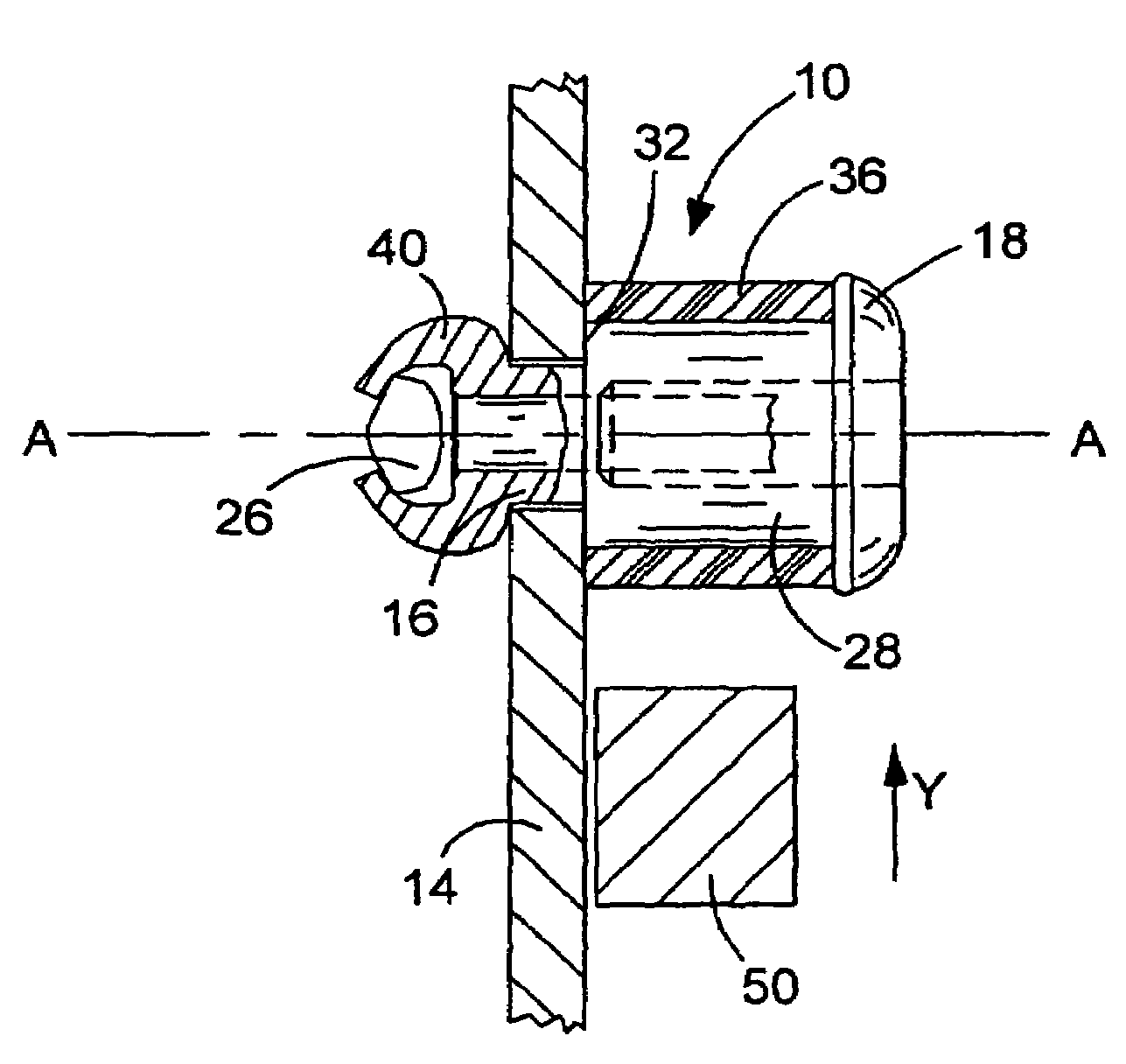
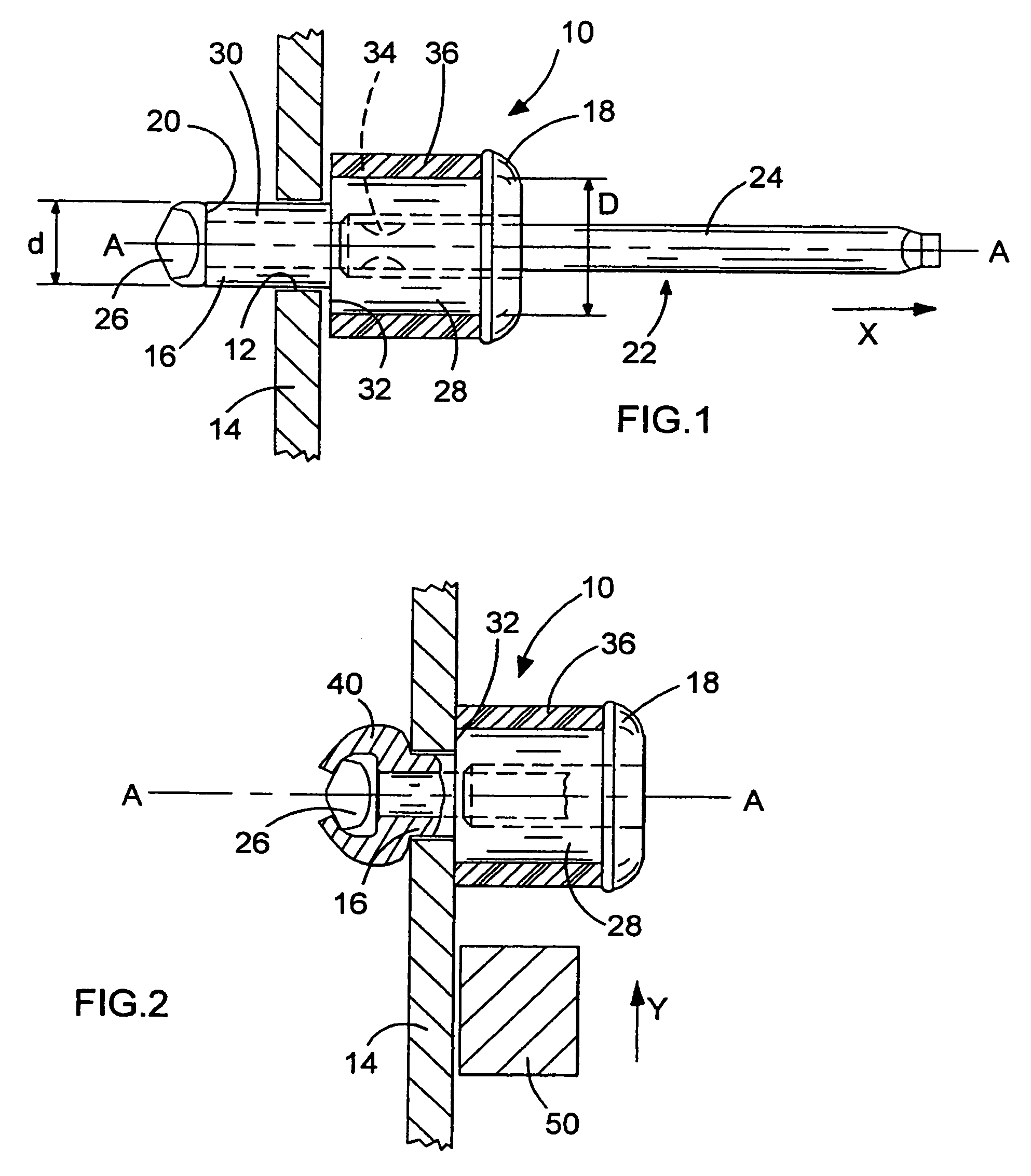
[0012]Referring now to FIG. 1, there is shown a shock absorbing blind rivet (10) comprising a conventional open end blind rivet operational structure. This blind rivet (10) is illustrated inserted through a pre-formed hole (12) in a specific workpiece (14) which, in this specific embodiment will comprise a metal track of a window winder construction for a motor vehicle. The rivet (10) is shown prior to undertaking a blind rivet setting operation.

[0013]The blind rivet (10) comprises an elongate, substantially tubular (or cylindrical), rivet body (16) having an enlarged radially extending flange (18) disposed at one end of the rivet body (16). As is conventional, the flange (18) forms a shoulder extending substantially perpendicular to a central axis A of the blind rivet assembly (10). The remote tail end (20) of the rivet body (16), axially opposed to the flange (18), has a substantially flat end face extending substantially perpendicular to the rivet axis (A).

[0014]As is conventiona...


PUM


Abstract

The present invention is directed to a blind fastener, usually a blind rivet, (10) comprising a mandrel (22) and an elongate cylindrical body (16) mounted on a stem (24) of such mandrel so as to extend co-axially about a central axis A of such blind rivet, the body (16) having a flange (18) at one end and a tail end (20) at an axially opposed end, for insertion through a hole in a workpiece, the mandrel having a mandrel head (26) in operative engagement with this tail end (20) for transmitting force thereto during setting of such fastener, wherein the body (16) has two different external diameters (d, D) and a radially extending shoulder (32) therebetween such that the external diameter (D) of the body adjacent to the flange (18) is greater than the external diameter (d) of the body adjacent to the tail end, wherein the body between this shoulder (32) and the flange is at least partially encased in a resilient, shock absorbing material (36).

Description

BACKGROUND OF THE INVENTION[0001]The present invention relates to tubular blind fasteners of the type that can be inserted through a pre-formed hole in a workpiece and secured therein by a setting operation carried out from one side of such workpiece. More particularly, this invention is directed to a blind fastener utilising a pull mandrel to effect the setting operation and which further has shock absorbing properties.[0002]Many conventional assemblies, across through many different industries, utilise end-stops defining the limit of movement of particular slidable members. One example of such a stop member is an end-stop for sliding drawers in cabinets, desks and domestic cooker trays. Additionally, within the motor industry, it is known that the plastic carrier part of an electric window assembly (the carrier part that supports and carries the glass in a window winder application) travels along an appropriate metal track that acts as a guide for such carrier. The movement of the...

Claims


Application Information

Patent Timeline
Patent Type & Authority Patents(United States)
IPC IPC(8): F16B19/00B60J1/17F16B13/04F16B19/08F16B19/10
CPCF16B19/1054Y10S411/903F16B19/04
Inventor JONES, STEVEN V.WEEKS, GEOFFREY
Owner NEWFREY
Why Eureka
Try Eureka