Drive device for a windmill provided with two counter-rotative propellers

a technology of driving device and propeller, which is applied in the direction of propulsive elements, propellers, engine fuctions, etc., can solve the problems of inconvenient use of various mechanisms and affecting the speed at which the blades rotate, and achieve the effect of improving efficiency

Inactive Publication Date: 2008-06-10
EOTHEME
View PDF15 Cites 62 Cited by
  • Summary
  • Abstract
  • Description
  • Claims
  • Application Information

AI Technical Summary

Benefits of technology

[0009]One of the first goals of the present invention is to propose a drive device for an improved windmill composed of two counter-rotative sets of blades. First of all, its efficiency will be better than t...

Problems solved by technology

Moreover, he provided the possibility of combining the stators and rotors to regulate the generator's electric excitation, thereby affecting the spee...

Method used


Image

  • Drive device for a windmill provided with two counter-rotative propellers
  • Drive device for a windmill provided with two counter-rotative propellers
  • Drive device for a windmill provided with two counter-rotative propellers

Examples


first embodiment

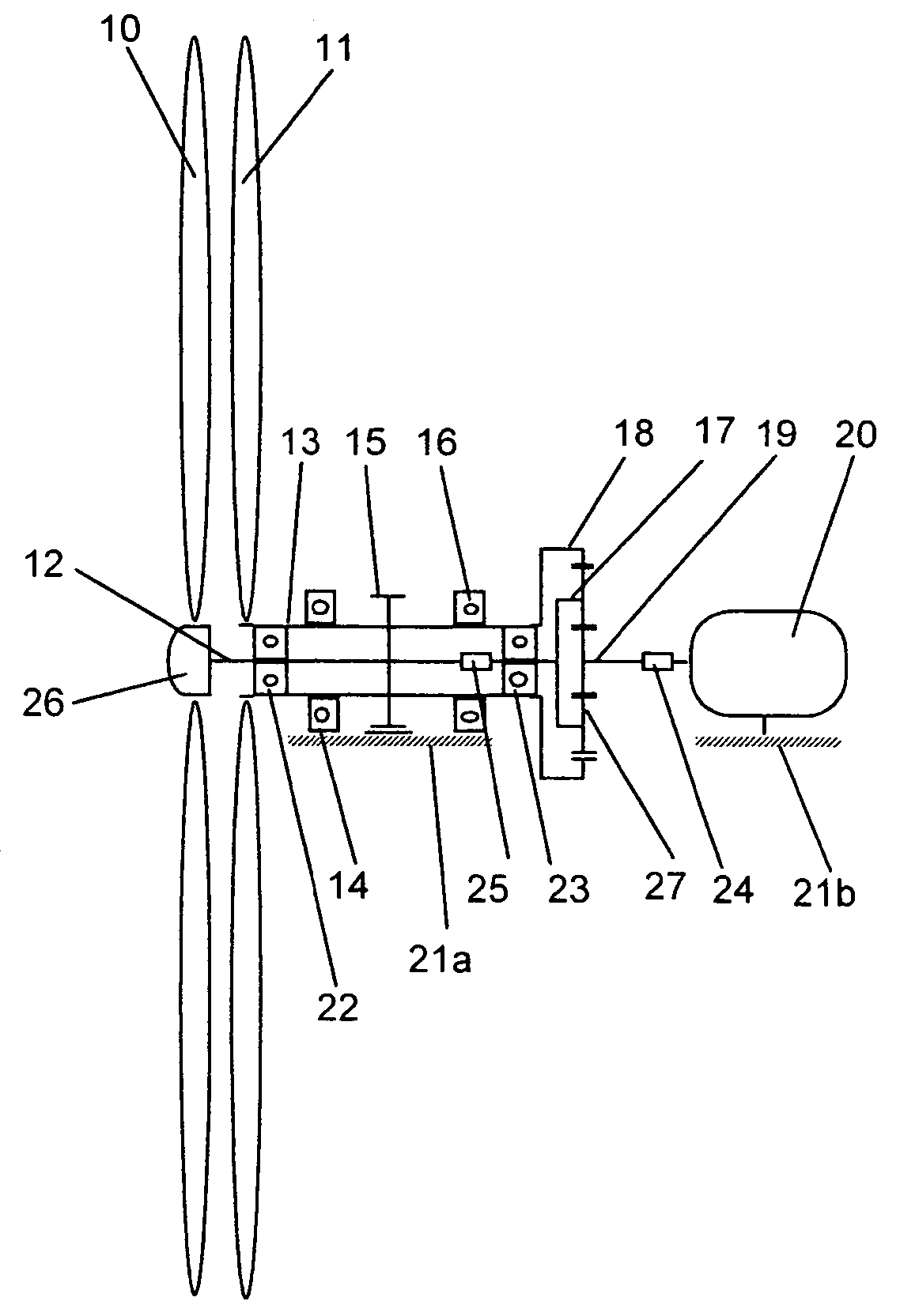
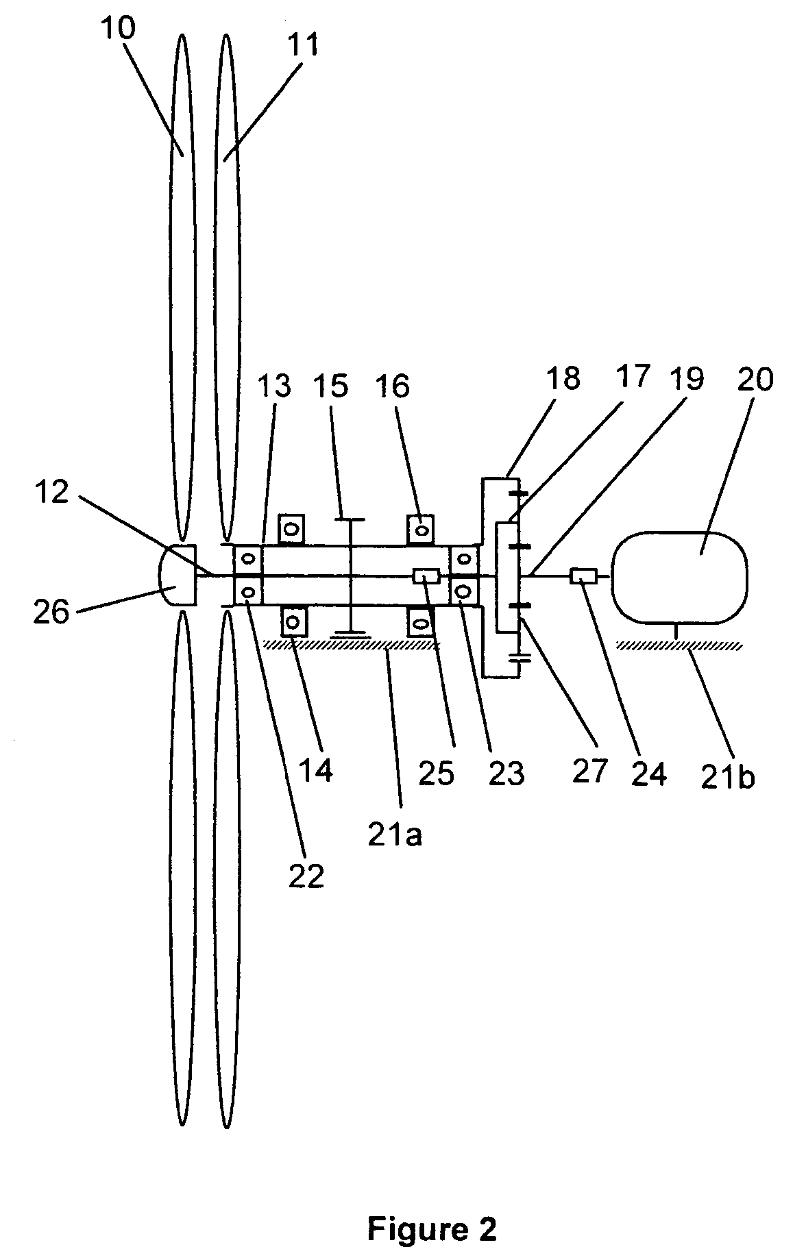
[0019]the drive device is indicated in FIG. 2. The first set of blades 10 and its hub 26 are supported by shaft 12, itself piloted by bearings 22 and 23 located inside hollow shaft 13. The second set of blades 11 is supported by hollow shaft 13, itself piloted by bearings 14 and 16. These two bearings 14 and 16, as well as portion 21a of the main armature of nacelle 8, are interdependent. Shafts 12 and 13 are coupled with an epicycloidal multiplier, wherein shaft 12 is coupled with train of planetary wheels 17, which in turn is linked to the epicycloidal multiplier; hollow shaft 13 is coupled with crown wheel 18 of the epicycloidal multiplier. The solar wheel activated by the epicycloidal multiplier is coupled with shaft 19, which in turn drives generator 20 through coupling 24. Since propellers 10 and 11 are counter-rotative, crown wheel 18 and train of planetary wheels 17 turn counter-rotatively as well. Power is therefore transmitted from shafts 12 and 13 to the generator shaft 1...

second embodiment

[0020]FIG. 3 provides the drive device proposed by the invention. In this case, the epicycloidal multiplier is directly implanted in the hub of one of the propellers. Propeller 10 is piloted by bearings 22 and 23 and is linked to shaft 12 through train of planetary wheels 17, while the train of wheels itself is implanted between the two bearings. Propeller 11 is directly mounted onto crown wheel 18, which in turn is connected to shaft 13 operated by bearings 14 and 16. Shaft 19 is linked on one side to the solar wheel, and on the other, to generator 20 through coupling 24.

[0021]Ultimately, both drive models function in similar ways.

[0022]The speed at which shaft 19 operates generator 20, as well as its drive couple are proportional to respectively the rotation speed and the couple yielded by propellers 10 and 11, respectively mounted on shafts 12 and 13. Propeller 10 and shaft 19 rotate in the same direction.

[0023]It will therefore be preferable that both propellers turn at the same...


PUM


Abstract

The drive device is provided for inclusion in a windmill with two counter-rotating screws. The shafts of the screws are each connected to a spindle of an epicyclical gearbox, the third spindle providing the energy for the user. The device further comprises a brake device simultaneously acting on the two shafts of the screws. In particular, said device permits the installation of a second screw on a windmill mast designed for a single screw on a windmill mast designed for a single screw, thus greatly increasing the power supplied.

Description

[0001]The content of Application PCT / CH2003 / 000625, filed Sep. 16, 2003, in Switzerland is hereby incorporated by reference.BACKGROUND OF THE INVENTION[0002]The present invention concerns an electrical generator's drive device, or that of any other mechanism that requires energy from a wind turbine provided with two counter-rotative propellers.PRIOR ART[0003]To this date, it is still common practice to commercialize windmills equipped with only one set of blades. Theoretically, the aerodynamic efficiency yielded by a single propeller cannot exceed 59.6% (Betz, A., “Wind-Energie und Ihre Ausnützung durch Windmuelen”, van den Hoeck & Ruprecht, Goettingen, 1926). In practice, the output is actually even weaker (between 40 and 45% in the best conditions).[0004]An attractive solution for higher global output consists in a mechanism including two counter-rotative sets of blades.[0005]Several documents offer methods or drive devices with two propellers. Schönball (U.S. Pat. No. 3,974,396 / 1...

Claims


Application Information

Patent Timeline
IPC IPC(8): F03D1/02
CPCF03D1/025F05B2260/40311Y02E10/72F03D9/25
Inventor WACINSKI, ANDRE
Owner EOTHEME
Why Eureka
Try Eureka