Flexible radio frequency identification label and method for fabricating the same

a radio frequency identification and label technology, applied in the field of flexible rfid labels, can solve the problems of inability to effectively apply radio frequency identification labels b>1/b> to objects having an uneven surface, adverse influence of product reliability, and inability to meet the requirements of miniaturization, so as to improve the moisture-proof effect and protect products, prevent oxidation, and increase product reliability

Inactive Publication Date: 2008-06-10
IND TECH RES INST
View PDF13 Cites 6 Cited by
  • Summary
  • Abstract
  • Description
  • Claims
  • Application Information

AI Technical Summary

Benefits of technology

[0007]In light of the above prior-art drawbacks, a primary objective of the present invention is to provide a flexible radio frequency identification label and a method for fabricating the same, by which the moisture-proof effect and protection of products can be improved.
[0008]Another objective of the present invention is to provide a flexible radio frequency identification label and a method for fabricating the same, by which a surface with satisfied flatness can be provided.
[0009]Still another objective of the present invention is to provide a flexible radio frequency identification label and a method for fabricating the same, by which a simple fabrication method is provided.
[0010]A further objective of the present invention is to provide a flexible radio frequency identification label and a method for fabricating the same, by which the cost can be minimized.
[0011]A further objective of the present invention is to provide a flexible radio frequency identification label and a method for fabricating the same, by which the service life of products can be extended.
[0020]When comparing to the prior-art, the flexible radio frequency identification label proposed in the present invention encapsulates the radio frequency identification circuit such as a chip or a printed circuit structure in the closed space. Thus, the radio frequency identification circuit can be completely protected and prevented from being oxidized due to moisture in the outside environment. In other words, the moisture-proof effect and protection of products can be improved to increase the product reliability and extend the service life of the product. As a flexible protection layer is used instead of a multi-layered structure, the overall radio frequency identification label is miniaturized and is able to maintain good flexibility. Thus, a sequence of fabrication processes can be easily performed and the radio frequency identification label can be applied to an object with an uneven surface. Moreover, as the structure such as the groove is located inside the flexible radio frequency identification label, surface flatness can be ensured to allow surface prints or other labels. Additionally, as the radio frequency identification circuit can be a printed circuit structure received in the closed space, prior-art processes such as dispensing and preheating can be eliminated, such that the fabrication method can be simplified to reduce production costs.

Problems solved by technology

However, it does not meet the requirement of miniaturization as its overall thickness is increased by its multi-layer design.
Furthermore, the increased thickness would also influence the flexibility of the radio frequency identification label 1, so that the radio frequency identification label 1 cannot be effectively applied to an object having an uneven surface.
When being used in a flexible condition or applied to an object having an uneven surface, the gap can be easily expanded, so that the moisture-proof effect and the reliability of products are adversely influenced as a consequence.
Additionally, the maintenance of the surface flatness and the inclusion of the upper lamination 21 and the lower lamination 22 result in an increase in the overall thickness of the radio frequency identification label 2, such that the flexibility of the label is decreased, resulting in limitation of application.
However, such radio frequency identification label 3 is also disadvantageous as it provides no protective or moisture-proof design.
Moreover, as the conductive material 33 is interposed between the integrated circuit 31 and the antenna 32, the surface flatness cannot be easily maintained, so that surface prints or other labels cannot be provided.

Method used


Image

  • Flexible radio frequency identification label and method for fabricating the same
  • Flexible radio frequency identification label and method for fabricating the same
  • Flexible radio frequency identification label and method for fabricating the same

Examples


first embodiment

[0029]FIG. 4 is a diagram of a flexible radio frequency identification label according to the first embodiment of the present invention. Referring to FIG. 4, a flexible radio frequency identification label 4 comprises a first flexible protection layer 43, a second flexible protection layer 41, a miniaturized antenna 45 and a radio frequency identification circuit 47. The first flexible protection layer 43 is attached to the second flexible protection layer 41 to form a closed space 49 therebetween. The radio frequency identification circuit 47 is received in the closed space 49. Also, the miniaturized antenna 45 is interposed between the first flexible protection layer 43 and the second flexible protection layer 41 and electrically connected to the radio frequency identification circuit 47.

[0030]The first flexible protection layer 43 and the second flexible protection layer 41 can be flexible substrates having dielectricity, and can be a flat structure made of the same or different ...

second embodiment

[0040]FIG. 5 is a diagram of a flexible radio frequency identification label according to the second embodiment of the present invention. As the present embodiment and the first embodiment only differ in the structural design of the closed space, in order to provide a succinct specification, the symbols of the same elements are remained unchanged and detailed description of the same structure and fabrication are omitted.

[0041]Referring to FIG. 5, a flexible radio frequency identification label 4′ comprises a first flexible protection layer 43, a second flexible protection layer 41, and a radio frequency identification circuit 47. The first flexible protection layer 43 is attached to the second flexible protection layer 41 to form a closed space 49 therebetween. The radio frequency identification circuit 47 is received in the closed space 49. As the miniaturized antenna is extreme small in size and interposed between the first flexible protection layer 43 and the second flexible prot...

third embodiment

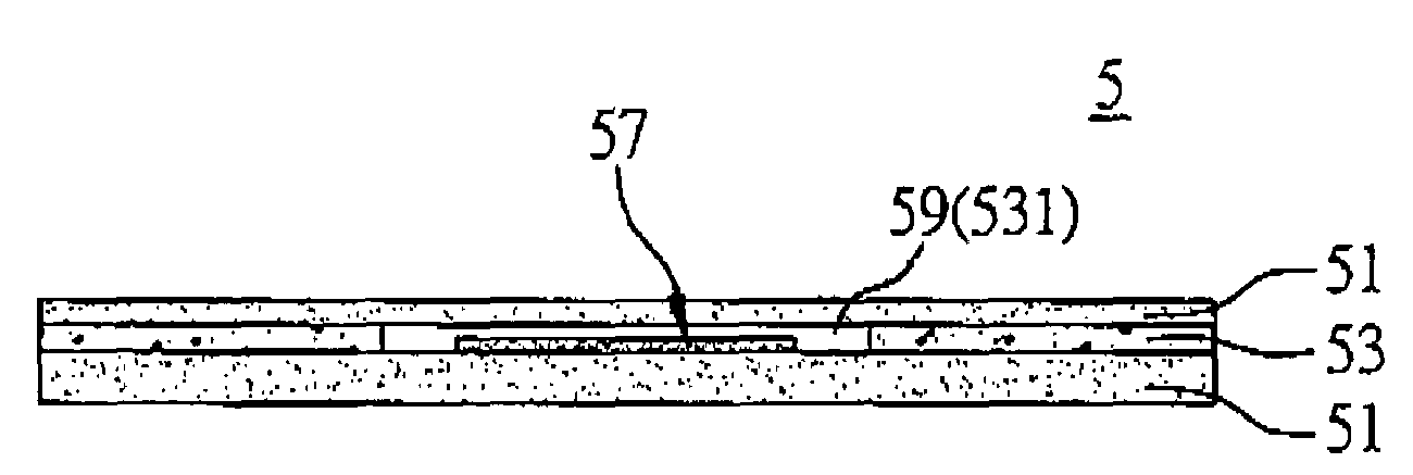
[0050]FIG. 6 is a diagram of a flexible radio frequency identification label according to the third embodiment of the present invention. Referring to FIG. 6, a flexible radio frequency identification label 5 comprises two flexible protection layers 51, a middle layer 53 having a hollow portion 531, a miniaturized antenna (not shown in the figure) and a radio frequency identification circuit 57. The two flexible protection layers 51 are attached to the middle layer 53 to form a closed space 59 therebetween. The radio frequency identification circuit 57 is received in the closed space 59. As the miniaturized antenna is extreme small in size and interposed between the two flexible protection layers 51, it is difficult to be labeled and indicated in the figure. It should be noted that its structure is the same as the one in the first embodiment, and it is also electrically connected to the radio frequency identification circuit 57 in the present embodiment.

[0051]The present embodiment m...


PUM


Abstract

A flexible radio frequency identification label and a method for fabricating the same are proposed. A first flexible protection layer is attached to a second flexible protection layer to form a closed space for receiving a radio frequency identification circuit. By such arrangement, a good flexibility can be provided by the flexible protection layers, and the closed space also enables the radio frequency identification circuit to be protected and isolated from the moisture in the outside environment, such that the circuit can be prevented from being oxidized and the service life of the product can be extended.

Description

FIELD OF THE INVENTION[0001]The present invention relates to radio frequency identification (RFID) labels and methods for fabricating the same, and more particularly, to a flexible RFID label and a method for fabricating the flexible RFID label.BACKGROUND OF THE INVENTION[0002]A radio frequency identification (RFID) label uses wireless data acquisition to identify and manage products. Because of a broad range of application, it is imperative to focus on ways to develop a radio frequency identification label, which enables mass production without being limited in its application. U.S. Pat. Nos. 6,262,692B1, 6,429,831, 6,275,156 and 6,094,138 have disclosed relevant radio frequency identification labels to meet its broad application.[0003]U.S. Pat. Nos. 6,262,692B1 and 6,429,831 have disclosed a radio frequency identification label having a multi-layered structure which comprises an antenna, a chip and a circuit connecting the antenna and the chip. Referring to a prior-art radio frequ...

Claims


Application Information

Patent Timeline
Patent Type & Authority Patents(United States)
IPC IPC(8): G08B13/14G06K19/06
CPCB29D22/00B32B37/185H01Q1/22H01Q1/2208H01Q1/38G06K19/07749B32B2305/342B32B2519/02Y10T156/103
Inventor SHIH, CHIN-MINGHSU, PIN-CHAOCHEN, YA-PINGMAI, JOHN D. H.
Owner IND TECH RES INST
Why Eureka
Try Eureka