Remote image display method, image capturing device, and method and program therefor
a technology of image capturing and remote image, which is applied in the direction of signal generators with optical-mechanical scanning, two-way working systems, and television systems. it can solve the problems of poor camera operability, inability to control the camera, and inability to achieve the desired image in some cases. achieve excellent camera operability
- Summary
- Abstract
- Description
- Claims
- Application Information
AI Technical Summary
Benefits of technology
Problems solved by technology
Method used
Image
Examples
embodiment 1
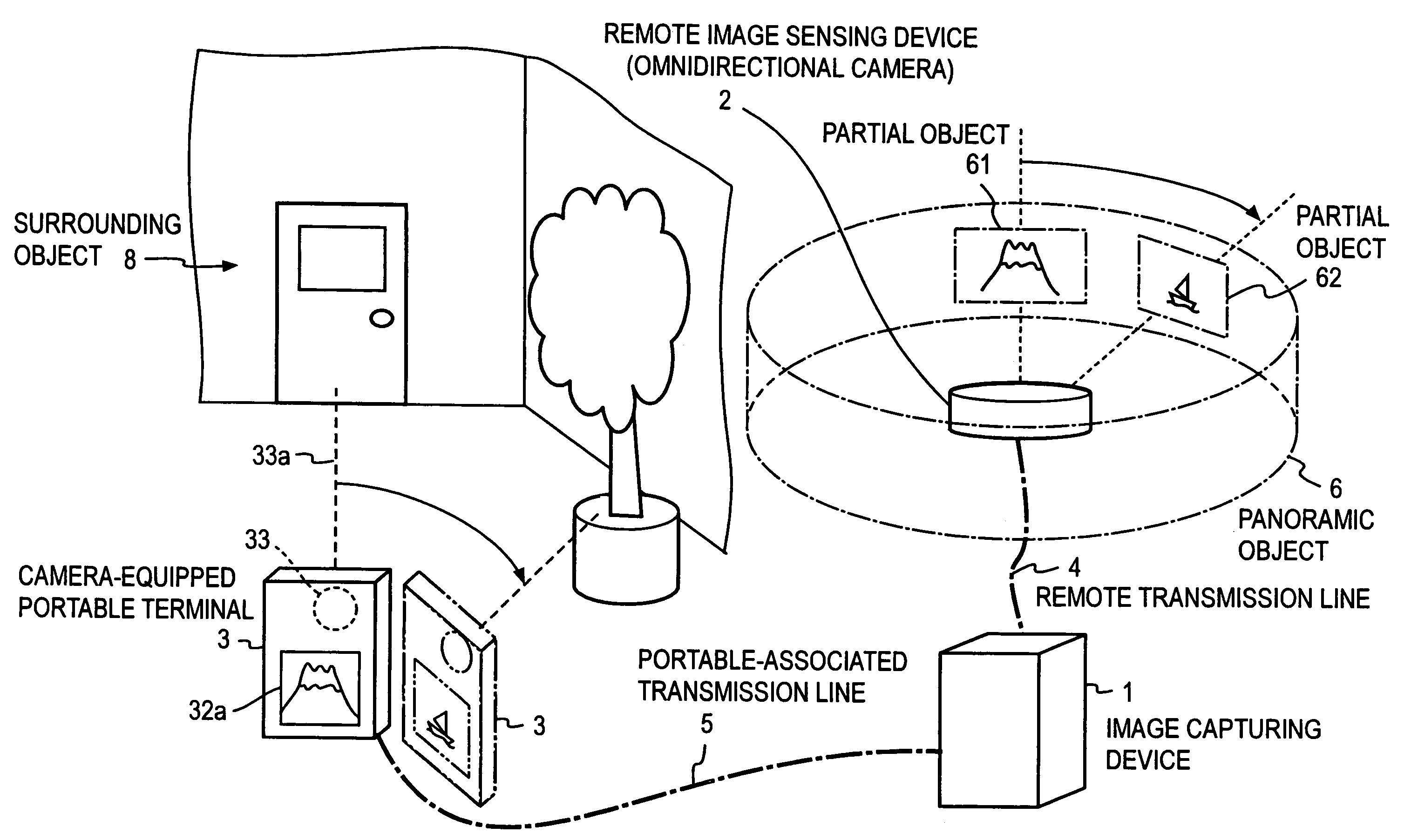
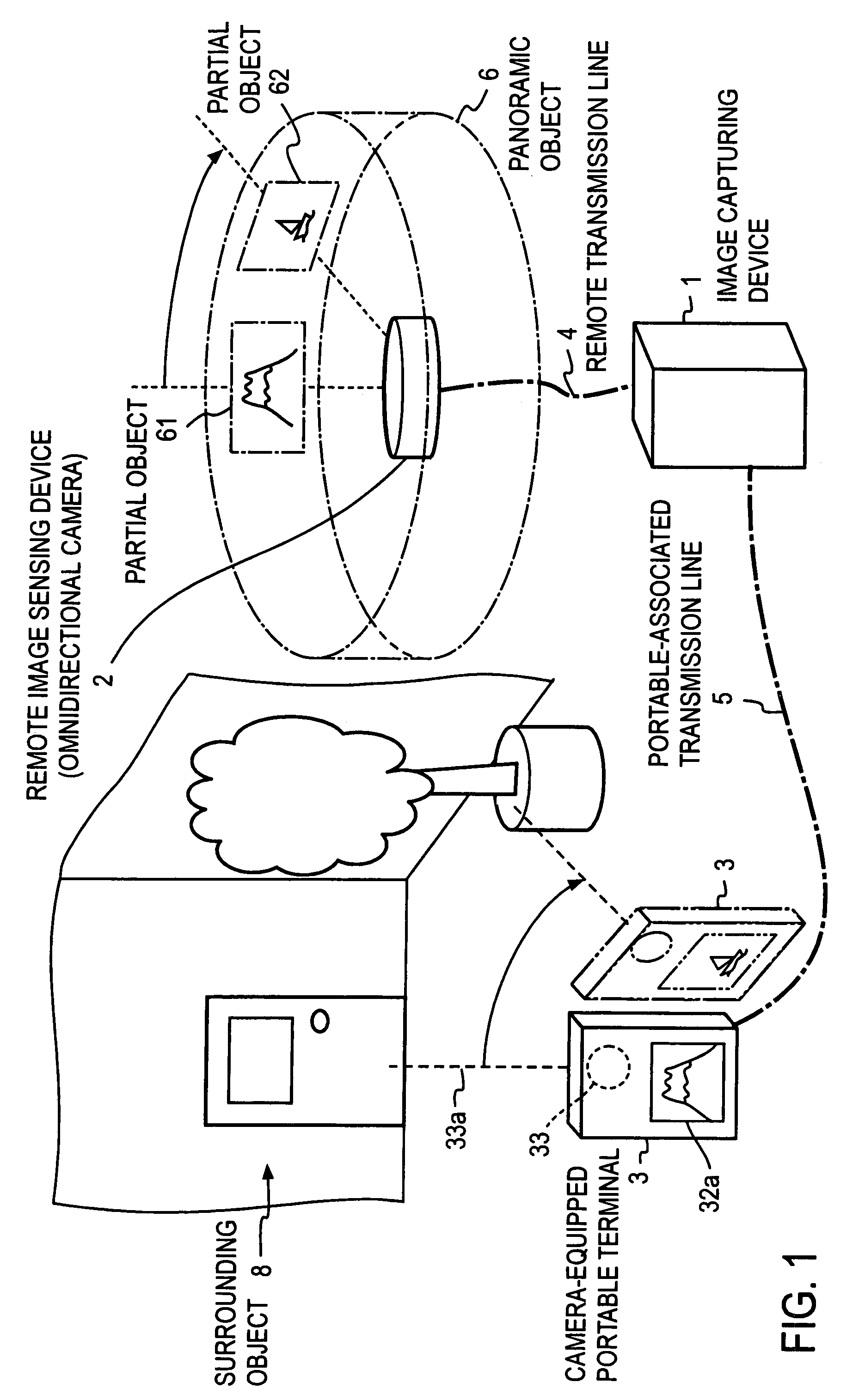
[0046]FIG. 4 illustrates in block form an example of the system configuration of Embodiment 1 of the present invention. In this application the same reference numerals denote parts of the same function and no duplicate description will be given of them.
[0047]The image capturing device 1 is provided with: surrounding image receiving means 11 that receives a surrounding video signal sent from the camera-equipped portable terminal 3 over the portable-associated transmission line 5; variation detecting means 12 that detects a variation in the image of the received surrounding video signal as variation information; capturing signal generating means 13 that generates a capturing signal based on the detected variation information; sending means 14 which sends the generated capturing signal to the remote image sensing device 2 over the remote transmission line 4; and image relay means 15 that receives the captured video signal sent from the remote image sensing device 2 over the remote tran...
embodiment 2
[0082]In Embodiment 1 the omnidirectional camera is used as the image sensing means of the remote image sensing device 2 and the image capturing device 1 sends the capturing signal to the remote image sensing device to cause it to extract the partial-object captured signal, but in Embodiment 2 an omnidirectional camera is used as image sensing means of the remote image sensing device 2, and the remote image sensing device 2 is caused to send all captured video signals to the image capturing device 1, and the image capturing device 1 extracts the partial-object captured signal from the received captured video signals.
[0083]FIG. 8 illustrate an example of the system configuration of this embodiment. The following description will be given only of the parts different from those in FIG. 4. In the remote image sensing device 2 the image extracting means 24 is omitted, and all the captured video signal of the omnidirectional camera 21 are sent from the video sending means 22 to the image ...
embodiment 3
[0087]Embodiment 3 uses a plurality of digital video cameras as image sensing means of the remote image sensing device 2, and the image capturing device 1 captures a video signal of a partial object in a panoramic object by extracting it in the remote image sensing device 2.
[0088]In FIG. 10 there are shown, by way of example, relationships between the remote image sensing device 2 and the panoramic object 6 in Embodiment 3. In this example, camera devices 21 to 28 having eight video cameras, as the remote image sensing device 2, are set over 360 degree with their shooting directions held at equal angular intervals. The viewing angles θ of the camera devices 21 to 28 each chosen to be a little larger than the angular distance of 45 degrees in this example so that the fields of adjacent camera devices partly overlap to permit image sensing continuous partial objects of the panoramic object. The panoramic object 6 forms a cylindrical surface at the same distance from the remote sensing...
PUM
 Abstract
Description
Claims
Application Information
 - R&D
- Intellectual Property
- Life Sciences
- Materials
- Tech Scout
- Unparalleled Data Quality
- Higher Quality Content
- 60% Fewer Hallucinations
Browse by: Latest US Patents, China's latest patents, Technical Efficacy Thesaurus, Application Domain, Technology Topic, Popular Technical Reports.
© 2025 PatSnap. All rights reserved.Legal|Privacy policy|Modern Slavery Act Transparency Statement|Sitemap|About US| Contact US: help@patsnap.com


