Constant current output using transconductance amplifier

a transconductance amplifier and constant current technology, applied in the direction of power conversion systems, instruments, dc-dc conversion, etc., can solve the problem of less precision in the average output current regulation

Active Publication Date: 2008-06-17
NAT SEMICON CORP
View PDF3 Cites 33 Cited by
  • Summary
  • Abstract
  • Description
  • Claims
  • Application Information

AI Technical Summary

Problems solved by technology

This leads to less precision in the

Method used


Image

  • Constant current output using transconductance amplifier
  • Constant current output using transconductance amplifier
  • Constant current output using transconductance amplifier

Examples


Embodiment Construction

[0039]FIGS. 5 through 17, discussed below, and the various embodiments used to describe the principles of the present invention in this patent document are by way of illustration only and should not be construed in any way to limit the scope of the invention. Those skilled in the art will understand that the principles of the present invention may be implemented with any type of suitably arranged electronic device.

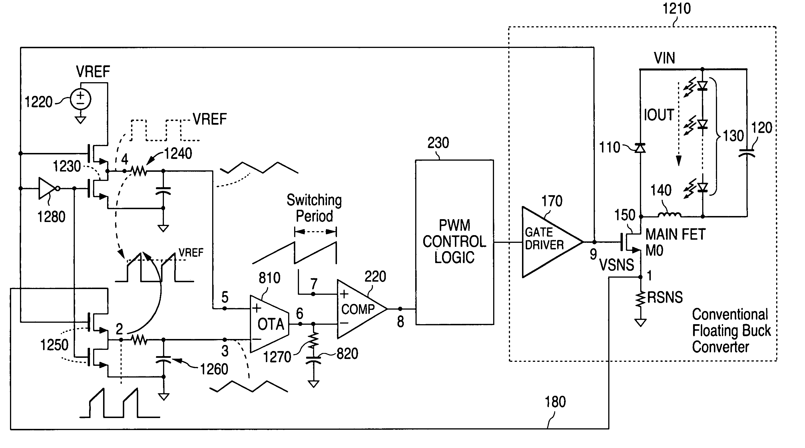
[0040]In particular, exemplary embodiments of the present invention will be described in a floating buck converter circuit. It is understood that the present invention is not limited to use in a floating buck converter circuit and that the principles of the present invention can also be employed in other types of devices.

[0041]The VSNS slope shown in FIG. 4(d) suggests that if one could regulate the mid-level of the VSNS slope of the VSNS voltage signal then one could regulate the direct current (DC) output current. The present invention comprises a system and method for a...


PUM


Abstract

An apparatus in an electronic device such as a buck converter circuit receives as a first input a voltage signal VSNS from the electronic device that represents a current through the electronic device, and receives as a second input a direct current reference voltage signal from a reference voltage source VREF. The apparatus regulates a direct current output IOUT of the electronic device with respect to the reference voltage source VREF by applying a pulse level transformation to the voltage signal VSNS using an operational transconductance amplifier.

Description

TECHNICAL FIELD OF THE INVENTION[0001]The present invention is generally directed to integrated circuit devices and, in particular, to a system and method for providing high efficiency precise constant current output in an electronic device.BACKGROUND OF THE INVENTION[0002]To better understand the advance in the art that the present invention provides a prior art floating buck converter circuit 100 will first be described. As shown in FIG. 1, prior art floating buck converter circuit 100 comprises the following elements: diode 110, capacitor 120, load 130, inductor 140, transistor 150 (here shown as a field effect transistor (FET) designated “MAIN FET M0”), resistor RSNS, pulse width modulation (PWM) control unit 160 and gate driver 170. The diode 110, capacitor 120 and the load 130 are coupled in parallel with a first end of each element coupled to the input voltage VIN. The load 130 shown in FIG. 1 comprises a plurality of serially connected light emitting diodes (LEDs). The outpu...

Claims


Application Information

Patent Timeline
IPC IPC(8): G05F1/575G05F1/62
CPCH02M3/156
Inventor LING, LAWRENCE HOK-SUN
Owner NAT SEMICON CORP
Why Eureka
Try Eureka