
Tandem-piston engine

a technology of piston engine and piston body, which is applied in the direction of piston engine, machine/engine, combustion engine, etc., can solve the problems of preventing the successful completion of the cycle, wasting as much heat, and not making maximum use of the heat generated, so as to prevent the absorption and wasting heat

Inactive Publication Date: 2008-06-24
NOLAND RONALD DEAN
View PDF3 Cites 12 Cited by
  • Summary
  • Abstract
  • Description
  • Claims
  • Application Information

AI Technical Summary

Benefits of technology

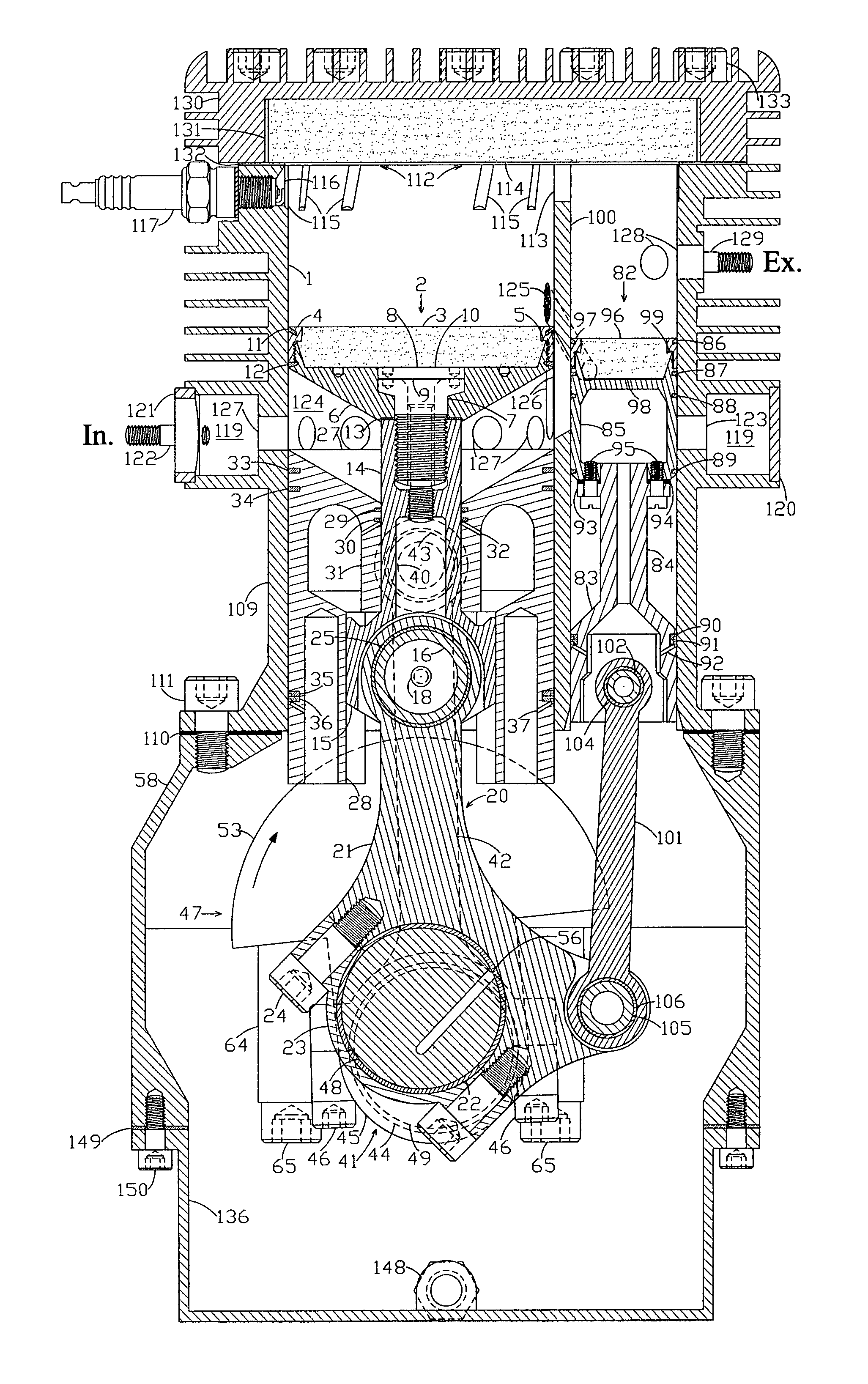
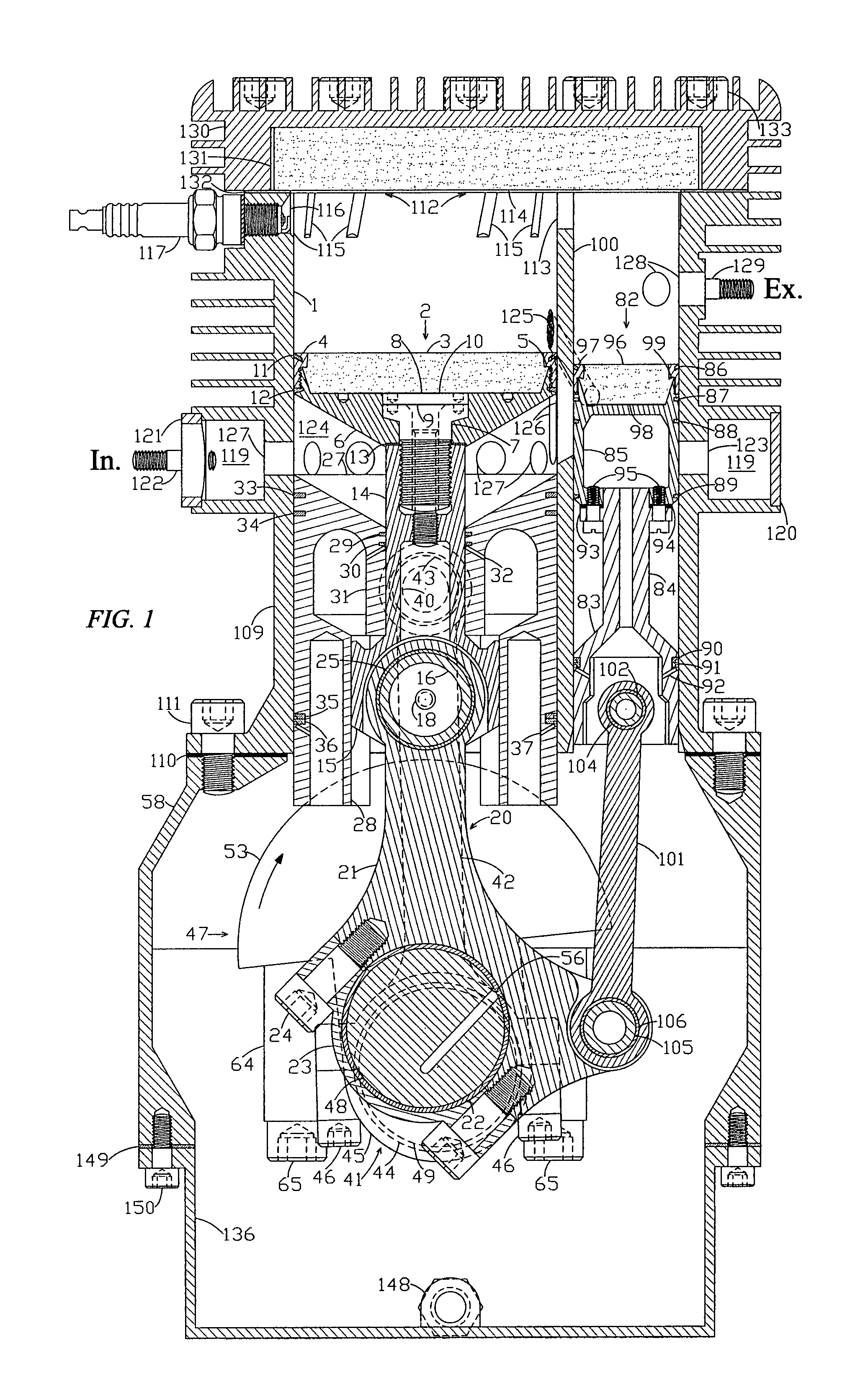
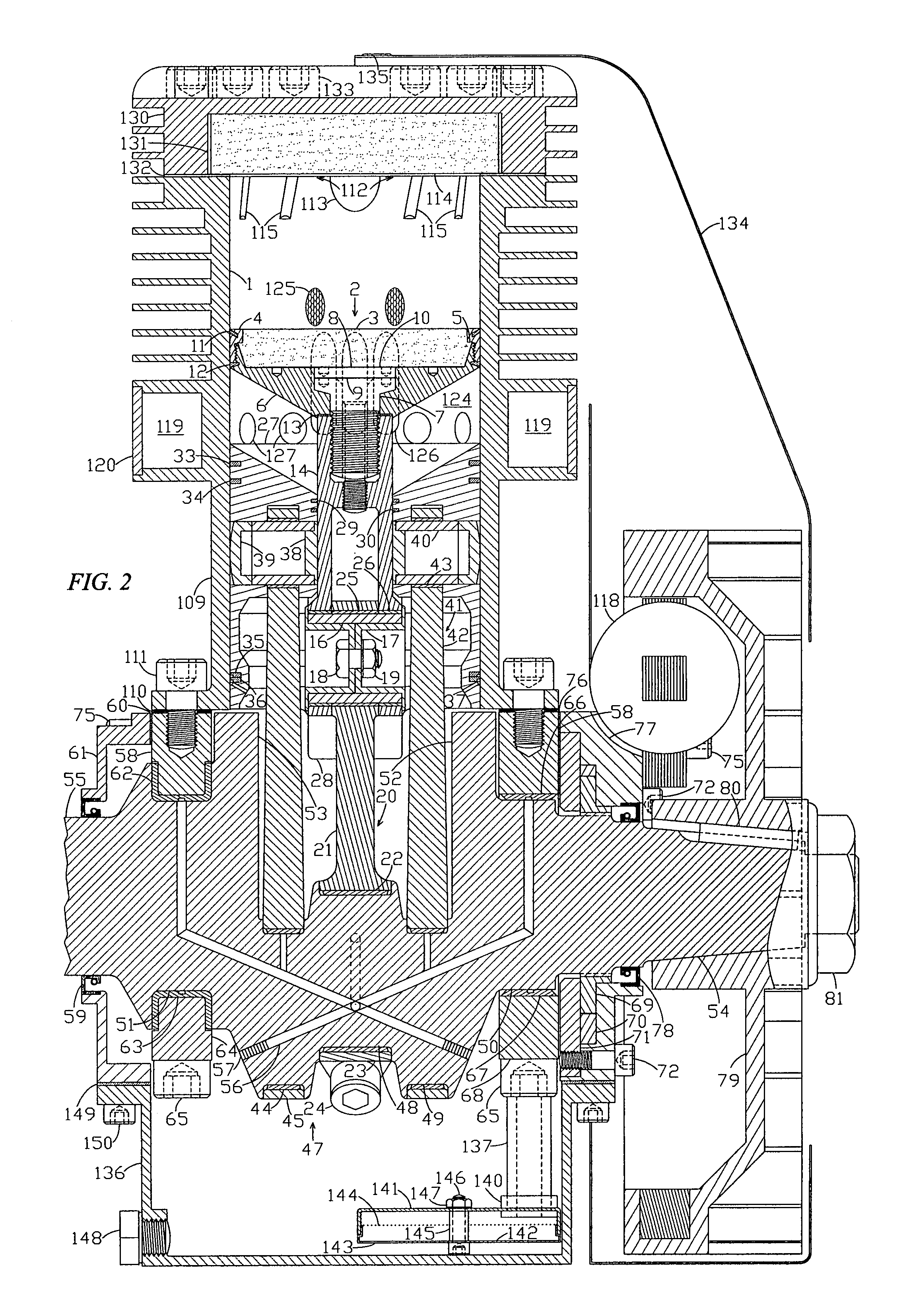
[0015]Thermal calculations then showed that far more insulation would be necessary to prevent heat loss from the combustion gases into the cylinder crown, piston crown and valve crown. These were redesigned to incorporate slabs of medium density zirconium phosphate of 19 mm (0.75 in.) for the cylinder crown and 12 mm (0.472 in.) for both the piston crown and the valve crown. This material is a machinable ceramic that is rated for use up to 1811 kelvin in air. It has a very low thermal conductivity, 0.9 watt / meter-kelvin, and a very low coefficient of thermal expansion, 0.9 micro-meter / meter-kelvin, which gives it an ultra high thermal shock resistance. The low coefficient of thermal expansion also allows it to be held in compression by clamping during high temperature operation. The bezels that hold the piston crown and valve crown were made of titanium for mass reduction and to use its low thermal conductivity to reduce the loss of heat from the combustion chamber.
[0017]The motor piston was also modified to give it a simple conical lower surface instead of the compound lower surface that was flat with a conical rim, which was used previously. This allows it to be thick in the center but much thinner at the outer edge thereby providing it with sufficient strength but less mass while it also reduces the length required for the transfer channels along the cylinder wall. The single conical surface is also easier to match with a single conical surface on the charger piston to effect total charge transfer.
[0019]The piston rod was redesigned to include a crosshead on its lower end that slides in a crosshead guide that is machined into the lower part of a redesigned charger piston so as to provide direct lateral support adjacent to the wrist pin. A strong lateral force is developed at the wrist pin as the motor connecting rod converts the vertical force from the piston rod into the rotaiy motion of the crankshaft. The lateral force will now be transmitted straight through the crosshead, the crosshead guide, and the wall of the charger piston to the cylinder wall without generating a twisting moment through the central piston rod boss. The original cantilever piston rod design lacked direct support for the lateral force at the wrist pin and it was thought that the force and wear might be excessive between the piston rod and piston rod boss. The new design should also effectively remove most lateral force from the motor piston. This arrangement is an improvement over the use of a conventional crosshead guide, which would need to be mounted in the cylinder block or upper part of the crankcase below the extent of piston travel, and which if used, would entail a substantial increase in the height of the engine. It would also entail an increase in the length of the charger connecting rods that would make them long and spindly. Another advantage of using a crosshead guide that is mounted in the charger piston is that the travel of the crosshead along a crosshead guide that is mounted in the charger piston is reduced to only the difference in stroke between the motor piston and the charger piston. In the present design, the stroke of the motor piston is two-thirds of the stroke of the charger piston so the travel of the crosshead along the crosshead guide is reduced to only one-half as much as it would be if the crosshead were to be mounted in the cylinder block in the typical fashion while the sliding velocity of the crosshead along the crosshead guide is also reduced by half. Another advantage of having the crosshead guide in the charger piston is that it is being pulled downward by the charger crankpins from the charger connecting rods while the motor piston is pushing the motor crankpin down through the piston rod and the motor connecting rod. Therefore the force that is transferred to the cylinder wall from the reaction at the wristpin from the motor rod is being reduced by the reaction at the piston pins from pulling the charger piston down thereby reducing the frictional losses even further. When totaled, the frictional losses are thus reduced to a small fraction of those encountered when using a crosshead guide mounted to the cylinder block.
[0022]2. It has insulated combustion chamber surfaces that operate at from 1000 to 1500 kelvin to prevent the absorption and wasting of as much heat from the hot combustion gases.

Problems solved by technology

Their mode of operation appears quite logical; but they do not make maximum use of the heat that is generated by the combustion of a fuel-air charge.
And the various two-stroke cycle gasoline engines in current use suffer from the same problem.
But paradoxically, in Otto cycle engines all parts of the combustion chamber must be kept reasonably cool.
Ignition then results in a backfire explosion through the intake manifold that prevents the successful completion of the cycle.
But even before any part becomes that hot, there will be preignition during the compression stroke that is likely to cause power loss, detonation and overheating of the piston and valves that can destroy the engine.
Since it is essential that the combustion chamber of these engines be kept cool, it is necessary to incorporate an air or liquid cooling system that usually adds substantially to their bulk and complexity and detracts from their reliability.
Increasing the expansion ratio will be of limited benefit in four-stroke spark-ignition engines where purging of heat from the combustion chamber is practiced because it is intrinsically necessary.
And it is unlikely that the mechanical efficiency will ever be much improved while a four-stroke engine requiring two revolutions per cycle, an extensive valve train and a mechanically pumped and fanned liquid cooling system is used.

Method used


Image

  • Tandem-piston engine
  • Tandem-piston engine
  • Tandem-piston engine

Examples


Embodiment Construction

[0048]Referring now to the drawings in detail, FIGS. 1 through 10. The engine has a main cylinder 1 that is fitted with a motor piston 2 of the crosshead type having a ceramic piston crown 3 that is clamped to it by a piston bezel 4. A conical upper surface on the piston-crown ledge 5 that has its vertex at the center of the lower surface of the piston crown is used by a mating conical lower surface on the piston bezel 4 to hold the piston crown 3 against a pistoncrown shim 10 that covers a titanium motor-piston base 6 and a locking-bolt 8. A piston-rod shim 13 is used to adjust the spacing of the motor-piston base 6 on a hardened and tempered steel piston rod 14 while a base bolt 7 clamps them together, and the locking bolt 8 with its height adjusted by a locking-bolt shim 9 prevents it from loosening. The piston-rod shim 13 must be chosen of the correct thickness to assure that the upper surface of the charger piston 27 firmly contacts the lower surface of the motor-piston base 6 ...


PUM


Abstract

The piston rod of the tandem-piston engine was modified to include a crosshead that slides in a crosshead guide machined into the lower part of the charger piston for better lateral support. The lower surface of the motor piston was changed to a simple conical surface allowing increased vertical thickness of the central region with a thinner outer region. A ceramic piston crown was clamped in compression by a piston bezel to the motor-piston base at a ledge with a conical upper surface having its vertex at the center of its base so thermal expansion will effect a sliding contact. A piston ring was used at the upper edge of the motor piston so the uppermost cylinder wall will be polished to prevent heat absorption. An intake port was given a flame arresting diffuser; and its entrance was blocked by the piston valve to prevent ignition in the valve cylinder.

Description

CROSS-REFERENCE TO RELATED APPLICATIONS[0001]Provisional Application No. 60 / 701,066 filed Jul. 21, 2005 by Ronald Dean Noland titled Tandem-Piston EngineSTATEMENT REGARDING FEDERALLY SPONSORED RESEARCH OR DEVELOPMENT[0002]Not applicableBACKGROUND OF THE INVENTION[0003]My invention relates to internal-combustion engines of the type employing a motor piston that reciprocates in a cylinder while turning a crankshaft for the extraction of motive power from the expansion of hot gases produced by the combustion of a compressed fuel-air charge that is supplied under pressure to a combustion chamber by a charger piston. A type fitting into the broad classification of two-stroke pump-compression cycle internal-combustion engines.[0004]Currently, most heat engines in use for mechanical power generation are of the four-stroke cycle type that was patented by Alphonse Beau de Rochas in 1862 and adapted for manufacture and practical use in 1876 by Nicolaus August Otto. These engines have been ver...

Claims


Application Information

Patent Timeline
Patent Type & Authority Patents(United States)
IPC IPC(8): F02B33/10
CPCF02B41/00F02B2075/025
Inventor NOLAND, RONALD DEAN
Owner NOLAND RONALD DEAN
Learn More