Card connector assembly having improved terminal

a technology of connector assembly and terminal, which is applied in the direction of coupling contact member, fixed connection, coupling device connection, etc., can solve the problems of unreliable electrical engagement with the inserted semiconductor/circuit board, and the terminal is not durable, and achieve the effect of reliable engagemen

Inactive Publication Date: 2008-06-24
HON HAI PRECISION IND CO LTD
View PDF11 Cites 30 Cited by
  • Summary
  • Abstract
  • Description
  • Claims
  • Application Information

AI Technical Summary

Benefits of technology

[0009]An object of the present invention is to provide a card connector assembly comprising a durable terminal having a reliable engagement with an electronic card.
[0011]The contact portions of the terminals could rotate toward the electronic card, for establishing a reliable engagement between the contact portions and the electronic card. The contact portions could also rotate outwardly for releasing the electronic card, to thereby ease the extraction of the electronic card. The terminals are durable since the contact portions apply a gradually increasing amount of normal force when the electronic card is fully inserted. It is of further benefit that the mating interface of the terminals rotate with respect to the conductive pads of the electronic card. In so doing, the wear area is distributed across a larger portion of the terminal interface. Durability and reliability are thus further improved.

Problems solved by technology

When the semiconductor / circuit board is inserted repeatedly, the connector terminals' conductive plating would experience excessive wear, resulting in unreliable electrical engagement with the inserted semiconductor / circuit board.
Further more, such a terminal is nondurable for mating cycles exceeding 250 cycles.

Method used


Image

  • Card connector assembly having improved terminal
  • Card connector assembly having improved terminal
  • Card connector assembly having improved terminal

Examples


Embodiment Construction

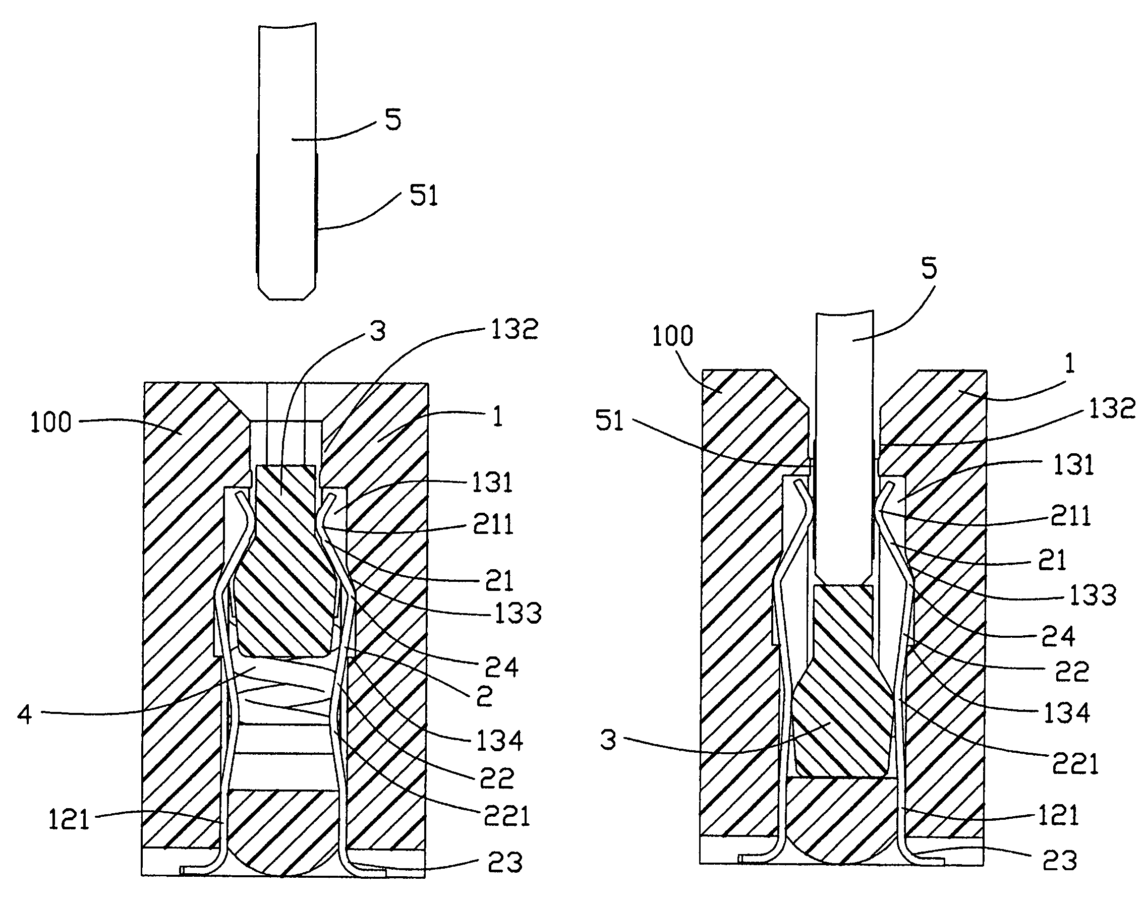
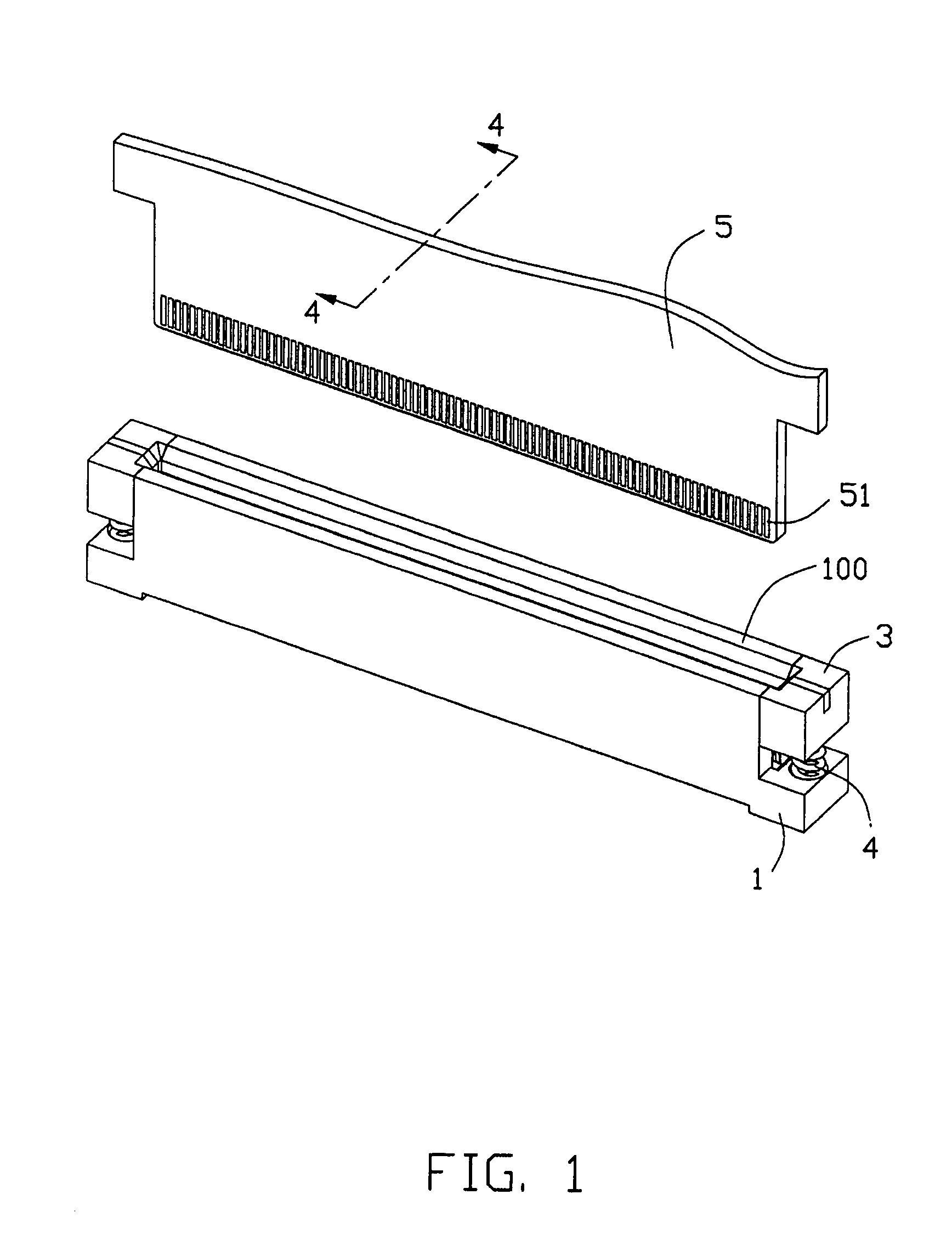
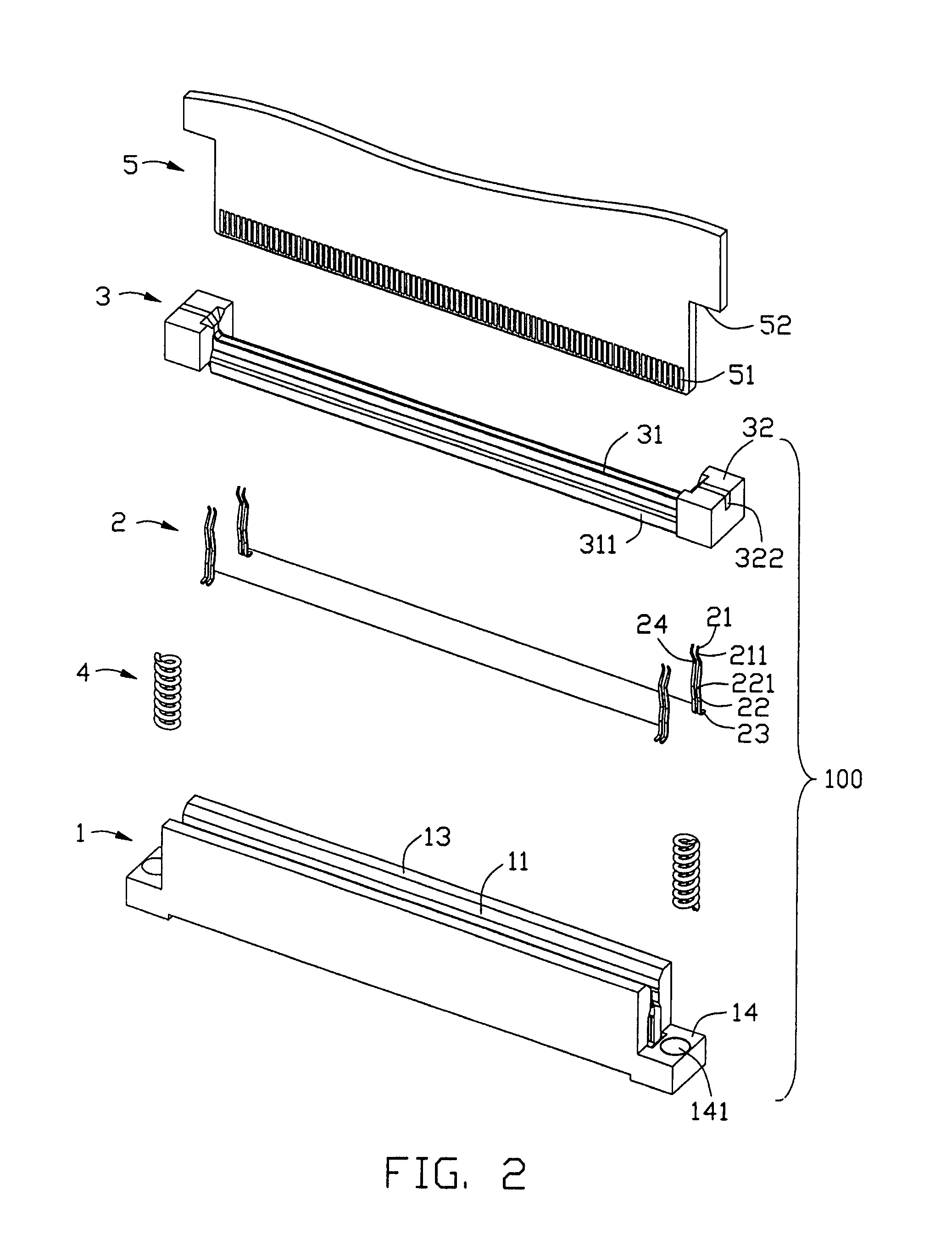
[0019]Reference will now be made to the drawing figures to describe the present invention in detail. Referring to FIGS. 1-6, a card connector assembly 100 in accordance with the preferred embodiment of the present invention is adapted for insertion of an electronic card 5. The card connector assembly 100 comprises an insulative housing 1, a plurality of terminals 2 assembled to the insulative housing 1, a carriage component 3, and a pair of coil springs 4 compressed between the carriage component 3 and the insulative housing 1.

[0020]Referring to FIGS. 2, 3, the insulative housing 1 comprises a rectangular base portion 12, a pair of periphery walls 13 upstanding from opposite sides of the base portion 12 and spaced apart from each other, an elongated slot 11 defined between the pair of separated periphery walls 13 and exposed to the outside in a longitudinal direction, and a pair of ear portions 14 projecting outwardly from opposite ends of the base portion 12. The periphery walls 13...


PUM


Abstract

A card connector assembly (100) for insertion of an electronic card (5), includes an insulative housing (1) defining therein a slot (11) and a number of passageways (131) communicating with the slot, and a number of terminals (2) retained in the passageways. Each terminal includes a contact portion (21) exposed in the slot for contacting with the electronic card, and a deformable resilient beam (22) having a depressible portion (221) away from the contact portion. The depressible portions are outwardly depressed due to an insertion of the electronic card, and are inwardly relaxed due to an extraction of the electronic card.

Description

CROSS-REFERENCE TO RELATED APPLICATIONS[0001]This patent application is a continuation-in-part of a U.S. patent application Ser. No. 11 / 634,490, filed on Dec. 6, 2006, now U.S. Pat. No. 7,338,303 and entitled “CARD CONNECTOR ASSEMBLY HAVING CARRIAGE COMPONENT”, which is invented by the same inventor as this patent application and assigned to the same assignee with this application.BACKGROUND OF THE INVENTION[0002]1. Field of the Invention[0003]The present invention relates to a card connector assembly, and particularly to a card connector assembly detachably receiving an electronic card.[0004]2. Description of Related Art[0005]A connector described in U.S. Pat. No. 6,213,804 was issued on Apr. 10, 2001. The connector for receiving a semiconductor comprises a housing defining an insertion slot for insertion of the semiconductor, a plurality of terminals assembled lengthwise along opposite sides of the insertion slot, and a driving mechanism. The driving mechanism comprises a carriage...

Claims


Application Information

Patent Timeline
Patent Type & Authority Patents(United States)
IPC IPC(8): H01R11/22
CPCH01R12/57H01R12/87H01R12/7082H01R12/714H01R12/716H01R12/721
Inventor SABO, JAMES M.
Owner HON HAI PRECISION IND CO LTD
Why Eureka
Try Eureka