Method and system for lattice space engineering

a technology of space engineering and lattice, applied in the field of integrated circuits, can solve the problems of reducing reducing the number of threading dislocation density (tdd), and high cost of integrated circuit or chip fabrication facilities, etc., to achieve the effect of reducing the number reducing the cost of integrated circuit or chip fabrication, and improving the yield of dies per wafer

Inactive Publication Date: 2008-06-24
SILICON GENERAL CORPORATION
View PDF21 Cites 22 Cited by
  • Summary
  • Abstract
  • Description
  • Claims
  • Application Information

AI Technical Summary

Benefits of technology

[0013]Many benefits are achieved by way of the present invention over conventional techniques. For example, the present technique provides an easy to use process that relies upon conventional technology. In some embodiments, the method may provide higher device yields in dies per wafer. Additionally, the method provides a process that is compatible with conventional process technology without substantial modifications to conventional equipment and processes. Preferably, the method provides for certain regions of silicon that strained using a novel support member. More preferably, the invention provides a resulting thin film structure, which has been strained, that is substantially free from dislocations, and other imperfections. Preferably, the invention provides for strained silicon-on-silicon structures that substantially reduces threading dislocation density (TDD) issues. Additionally, the invention provides a resulting substrate with strain that is unlikely to relax for any area size while the strain may relax for conventional strained SOI areas during subsequent integrated circuit processing, which often requires high temperatures according to a specific embodiment. Additionally, the present invention provides a resulting structure substantially free from underlying dislocation rich germanium bearing layers or other undesirable impurities that may lead to problems with device quality and / or reliability according to other embodiments. A substantially planar strained material (e.g., silicon) surface may also be achieved using certain embodiments of the present invention. Depending upon the embodiment, one or more of these benefits may be achieved. These and other benefits will be described in more throughout the present specification and more particularly below.

Problems solved by technology

An integrated circuit or chip fabrication facility can cost hundreds of millions, or even billions, of U.S. dollars.
Making devices smaller is very challenging, as each process used in integrated fabrication has a limit.
Additionally, as devices require faster and faster designs, process limitations exist with certain conventional processes and materials.
As devices become smaller, however, conventional bulk silicon has limitations.
These limitations include isolation problems between transistor device structures.
Additionally, conventional bulk silicon has imperfections, which lead to limitations with device speed and reliability issues.

Method used


Image

  • Method and system for lattice space engineering
  • Method and system for lattice space engineering
  • Method and system for lattice space engineering

Examples


Embodiment Construction

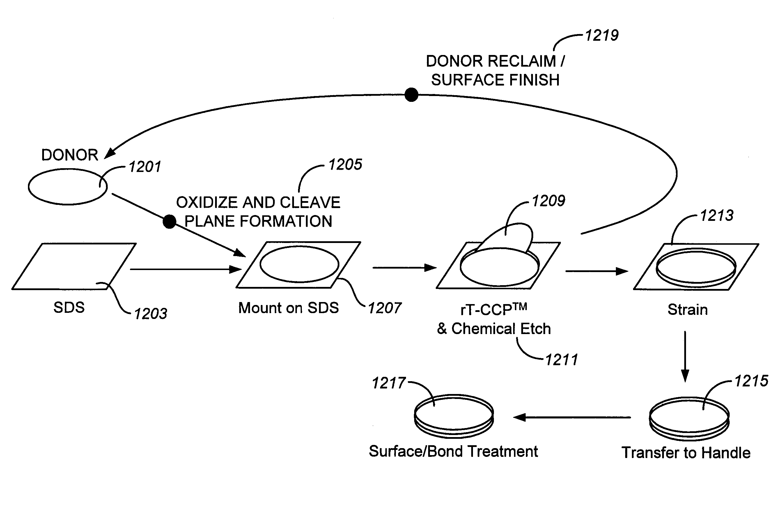
[0021]According to the present invention, techniques directed to integrated circuits and their processing for the manufacture of semiconductor devices are provided. More particularly, the invention provides a method and structures for manufacturing strained film(s) of material using a layer transfer process. Merely by way of example, the invention has been applied to strained silicon bearing materials for semiconductor substrates. But it would be recognized that the invention has a much broader range of applicability.

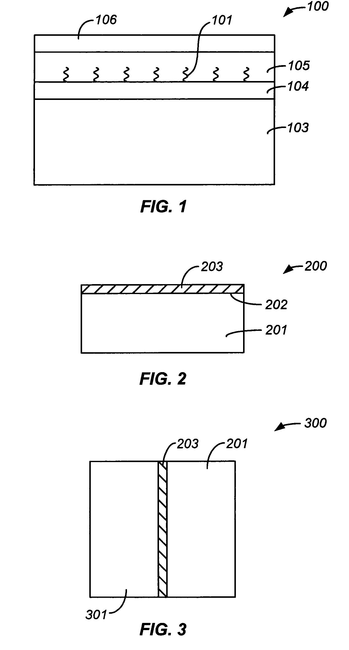
[0022]FIG. 1 is a simplified cross-sectional diagram of a conventional strained silicon substrate. As shown, the substrate 100 includes a semiconductor graded composition layer structure on the semiconductor substrate. The substrate 103 has a first semiconductor layer 104 having a series of lattice-mismatched semiconductor layers deposited on the substrate and annealed at a temperature greater than 100 degrees C. above the deposition temperature, a second semiconductor ...


PUM


Abstract

A system for manufacturing multilayered substrates. The system has a support member is adapted to process a film of material comprising a first side and a second side from a first state to a second state. The support member is attached to the first side of the film of material. The second state comprises a stressed state. The system has a handle substrate comprising a face, which is adapted to be attached to the second side of the film of material. The support member is capable of being detached from the first side of the film of material thereby leaving the handle substrate comprising the film of material in the second state being attached to the face of the handle substrate.

Description

CROSS-REFERENCE TO RELATED APPLICATIONS[0001]The present application claims priority to U.S. Provisional Application Nos. 60 / 561,762; 60 / 579,756 and 60 / 615,070, filed Apr. 12, 2004; Jun. 14, 2004 and Oct. 1, 2004, commonly assigned, and hereby incorporated by reference herein.BACKGROUND OF THE INVENTION[0002]The present invention is directed to integrated circuits and their processing for the manufacture of semiconductor devices. More particularly, the invention provides a method and structures for manufacturing strained film(s) of material using a layer transfer process. Merely by way of example, the invention has been applied to strained silicon bearing materials for semiconductor substrates. But it would be recognized that the invention has a much broader range of applicability.[0003]Integrated circuits have evolved from a handful of interconnected devices fabricated on a single chip of silicon to millions of devices. Conventional integrated circuits provide performance and compl...

Claims


Application Information

Patent Timeline
Patent Type & Authority Patents(United States)
IPC IPC(8): H01L21/30H01L21/46H01L21/00H01L21/20H01L21/762
CPCH01L21/2007H01L21/76251
Inventor HENLEY, FRANCOIS J.ONG, PHILIP JAMESMALIK, IGOR J.
Owner SILICON GENERAL CORPORATION
Why Eureka
Try Eureka