Ion guides with RF diaphragm stacks

a diaphragm and diaphragm technology, applied in the direction of instruments, particle separator tube details, separation processes, etc., can solve the problems of not actively driving ions forward without complicated additional measures, ions are not, and the embodiment of the ion funnel that has become familiar is particularly disadvantageous

Active Publication Date: 2008-06-24
BRUKER DALTONIK GMBH & CO KG
View PDF14 Cites 55 Cited by
  • Summary
  • Abstract
  • Description
  • Claims
  • Application Information

AI Technical Summary

Benefits of technology

[0013]The stack of diaphragms is thus characterized by hole shapes that do not simply create cylindrical or conical inner spaces with reflective walls for ions by pseudopotentials inside the stack, but which exercise specific effects on the shape of the ion beam inside the diaphragm stack. Diaphragm stacks whose diaphragms have apertures shaped in accordance with the invention are able not only to actively drive the ion beam forward, but are also able to shape its cross section. In combination with a damping and cooling gas in the diaphragm stack, the ions can be cooled and, in diaphragm stacks with suitable aperture shapes, can be collected in particular regions of the internal space. Active forward drive of the ions inside the diaphragm stack has been known for a long time, but the shaping of the ion beam has not. In particular it is possible, with special shapes and arrangements of the apertures, to collect the cooled ions along the axis of the diaphragm stack.
[0016]The forward drive inside the stack may not be directed in one direction only. It is possible, to force ions to oscillations in longitudinal direction, for instance, to fragment ions by multiple collisions with the damping gas. Even the formation of a potential well in axial direction inside the stack is possible, enabling ions to oscillate in this potential well in axial direction. In another example, the ions may be moved through the stack of diaphragms in pulses, to eject ions in a timely manner. Even the application of traveling wave fields or other traveling potential profiles is possible.
[0018]Appropriate shaping of the apertures in the diaphragms can also be used to give the ion beam other cross-sectional shapes. A series of tapering slit diaphragms can be used to generate beams with an elliptical cross section. Suitable shaping of the diaphragm holes can even be used, to lead an ion funnel to a beam divider, in which the beams emerge from two apertures at the end of the diaphragm stack. If two small quadrupole diaphragm stacks are positioned behind the holes, two very fine ion beams can be created.

Problems solved by technology

Their disadvantage is that they do not actively drive the ions forward without complicated additional measures.
They have, however, the disadvantage that, even in the presence of a cooling damping gas, the ions are not collected along the axis of the annular diaphragm system, since the pseudo-force that repels the ions only exerts its effect close to the outer wall of the cylinder or cone created by the diaphragm openings.
The embodiment of the ion funnel that has become familiar is particularly disadvantageous from this point of view.
The published embodiment has the disadvantage that only a relatively narrow band of specific masses passes through.
On the other hand, too much gas will enter into the next differential pump stage if the diaphragm openings at the final exit of the funnel are too large.
If large diaphragm openings are followed by an extraction lens with narrow openings to extract the ions from the ion funnel, the heavy ions cannot be extracted if the space charge is high, since they will be driven outward to the walls of the funnel and escape the drawing field of the extraction lens, which can only effectively extract ions out from the axis.
Manufacture of this quadrant funnel is, however, extraordinarily difficult and expensive.
These requirements cannot be satisfied by the stack of annular diaphragms constructed in the manner known at present, even though the possibility of actively driving the ions in the axial direction is a strong factor in favor of the use of diaphragm stacks.

Method used


Image

  • Ion guides with RF diaphragm stacks
  • Ion guides with RF diaphragm stacks
  • Ion guides with RF diaphragm stacks

Examples


Embodiment Construction

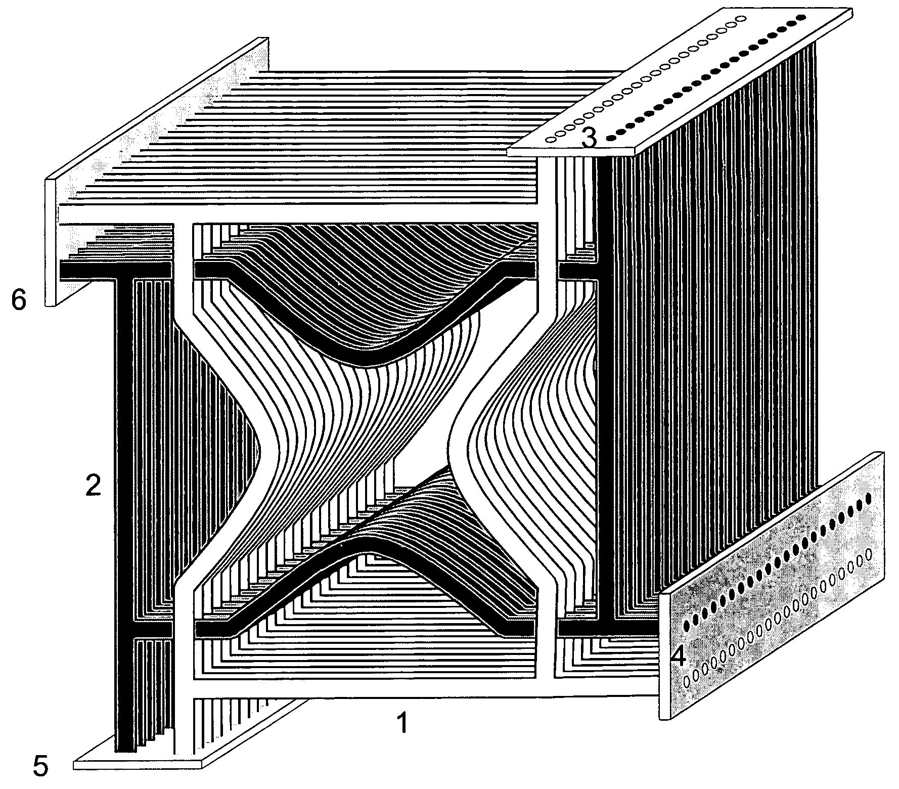
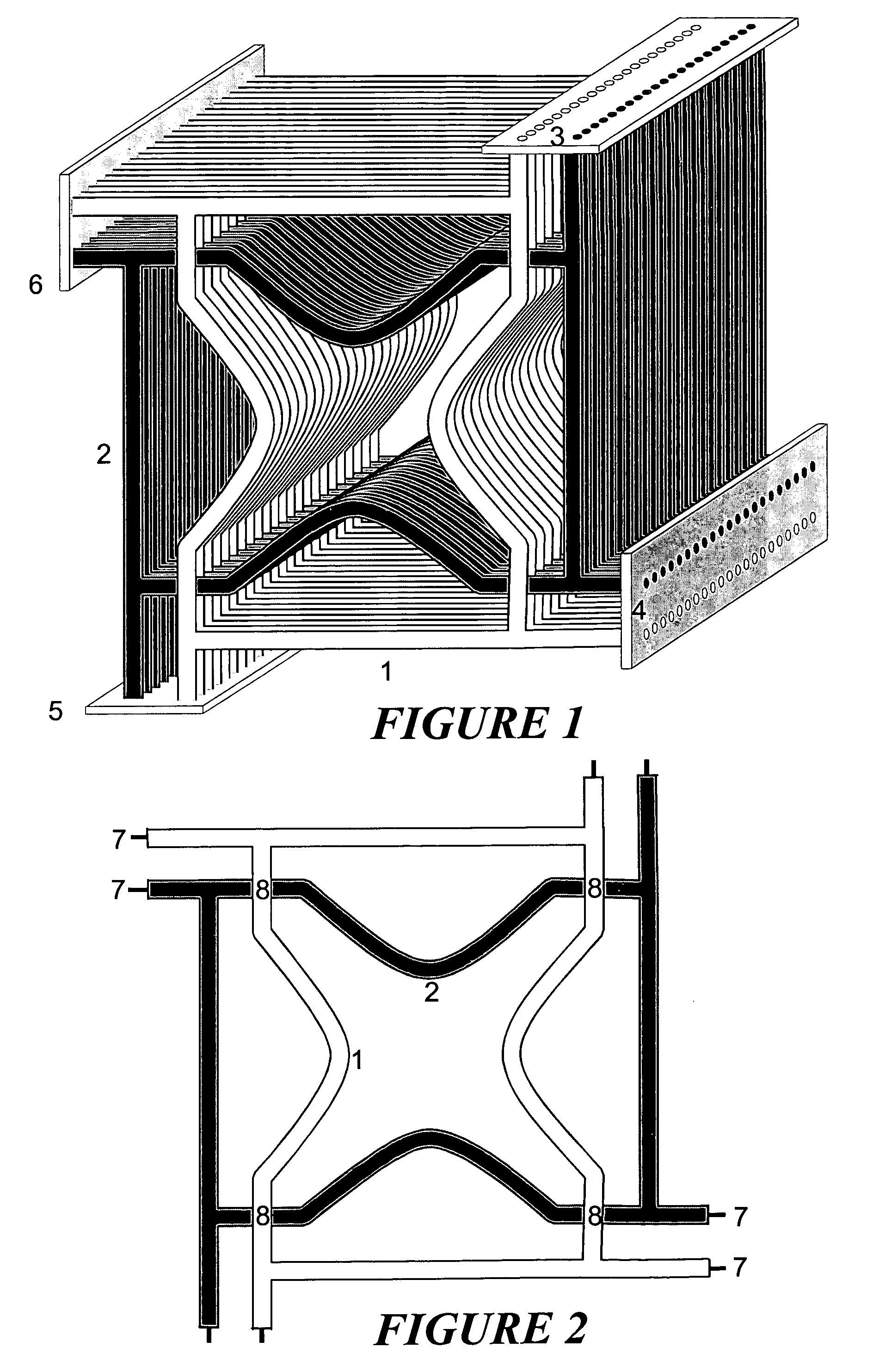
[0027]The invention provides special ion guides, based on stacks of apertured diaphragms, which not only drive the ion beam actively forward, but which are also able to shape its cross section. In connection with a damping and cooling gas, ions can be collected in particular regions of the interior of the diaphragm stack.

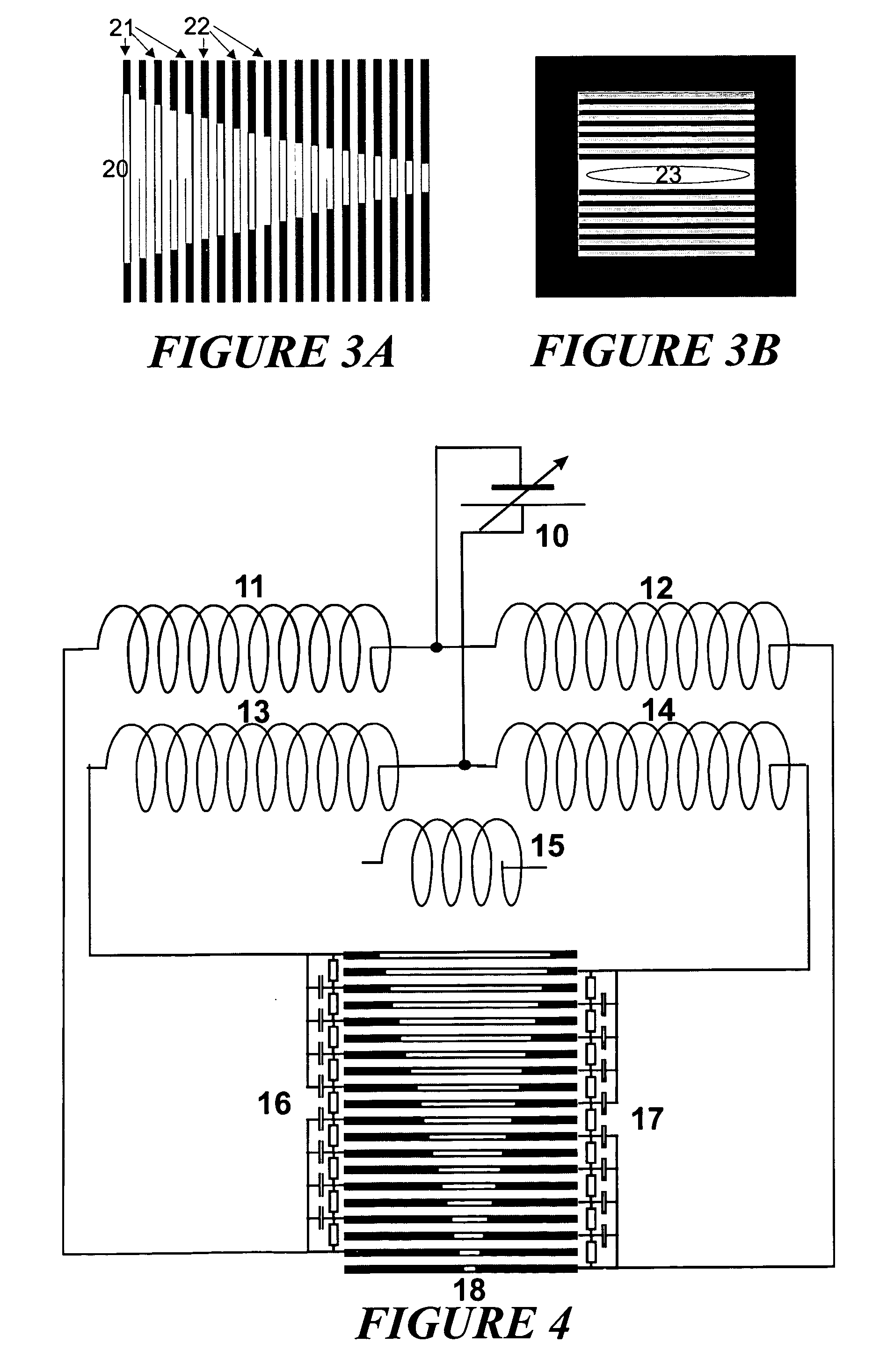
[0028]The characteristic property of the diaphragm stack in accordance with the invention is that, at least in part, it no longer contains the circular, coaxial holes in the diaphragms that until now have been exclusively used, but has diaphragms with oval, rectangular or even more complicated, even indented apertures. A further feature in accordance with the invention is that successive diaphragms, which are now no longer rotationally symmetrical, can each be arranged at a fixed angle with respect to one another. The features in accordance with the invention permit specific influence to be exerted on the ion beam, in particular influence on the cross-sectional shap...


PUM


Abstract

The invention relates to RF voltage-operated ion guides based on stacked apertured diaphragms. The invention provides ion guides consisting of diaphragm stacks that permit the ion beam to be shaped in cross-section so that it corresponds to the acceptance profile of the subsequent section of the device, therefore yielding optimal ion transmission. For this purpose, at least some of the diaphragms in the diaphragm stacks do not have circular openings, but instead have openings which shape the cross section of the emerging ion beam in the desired manner. It is possible, for instance, to obtain elliptical beam cross sections, divided beams or beams focused to the shape of a fine thread at the output of the diaphragm stacks.

Description

FIELD OF THE INVENTION[0001]The invention relates to RF voltage-operated ion guides based on stacked apertured diaphragms.BACKGROUND OF THE INVENTION[0002]Most ion guides consist of multipole structures, extending longitudinally, having rod-shaped pole pieces. Their disadvantage is that they do not actively drive the ions forward without complicated additional measures. For this reason, ion guides consisting of stacked diaphragms with circular apertures (known as “stacked rings”) are sometimes used for special purposes; an axial DC or modulated potential gradient permits the ions to be driven forward actively. Examples of this include ion funnels used to capture the ions from a gas flowing into the vacuum, collision cells with diaphragms of constant internal diameter and with active forward drive (“ion tunnels”), and ion packeting equipment using a traveling wave field to provide a forward drive of an ion beam with a desired time profile of ion density.[0003]For example, U.S. Pat. N...

Claims


Application Information

Patent Timeline
Patent Type & Authority Patents(United States)
IPC IPC(8): B01D59/44H01J49/00H01J49/06H01J49/42
CPCH01J49/065H01J49/42H01J49/04H01J49/06H01J49/4205
Inventor STOERMER, CARSTENBREKENFELD, ANDREASWEHKAMP, THOMASFRANZEN, JOCHEN
Owner BRUKER DALTONIK GMBH & CO KG
Why Eureka
Try Eureka