Methods for correction of spinal deformities

Active Publication Date: 2013-10-15
DEPUY SYNTHES PROD INC +1
View PDF69 Cites 27 Cited by
  • Summary
  • Abstract
  • Description
  • Claims
  • Application Information

AI Technical Summary

Benefits of technology

[0052]The use of the double function locking device in the method of the invention provides the additional advantage of enabling twisting forces to be applied to individual vertebrae before the channel is locked against movement relative to the rod. This can be achieved by applying twisting forces between the rod (which can be gripped using a tool such as a pair of pliers or grips, with appropriate jaws which are designed so as not to damage the sur

Problems solved by technology

Application of torsional forces to neutral vertebrae can result in some imbalance and unwanted movement of those vertebrae.
It can be challenging during a surgical procedure to implant a spinal support rod to ensure that appropriate forces are applied to a rod in order to deform it, so that appropriate bend

Method used


Image

  • Methods for correction of spinal deformities
  • Methods for correction of spinal deformities
  • Methods for correction of spinal deformities

Examples


Embodiment Construction

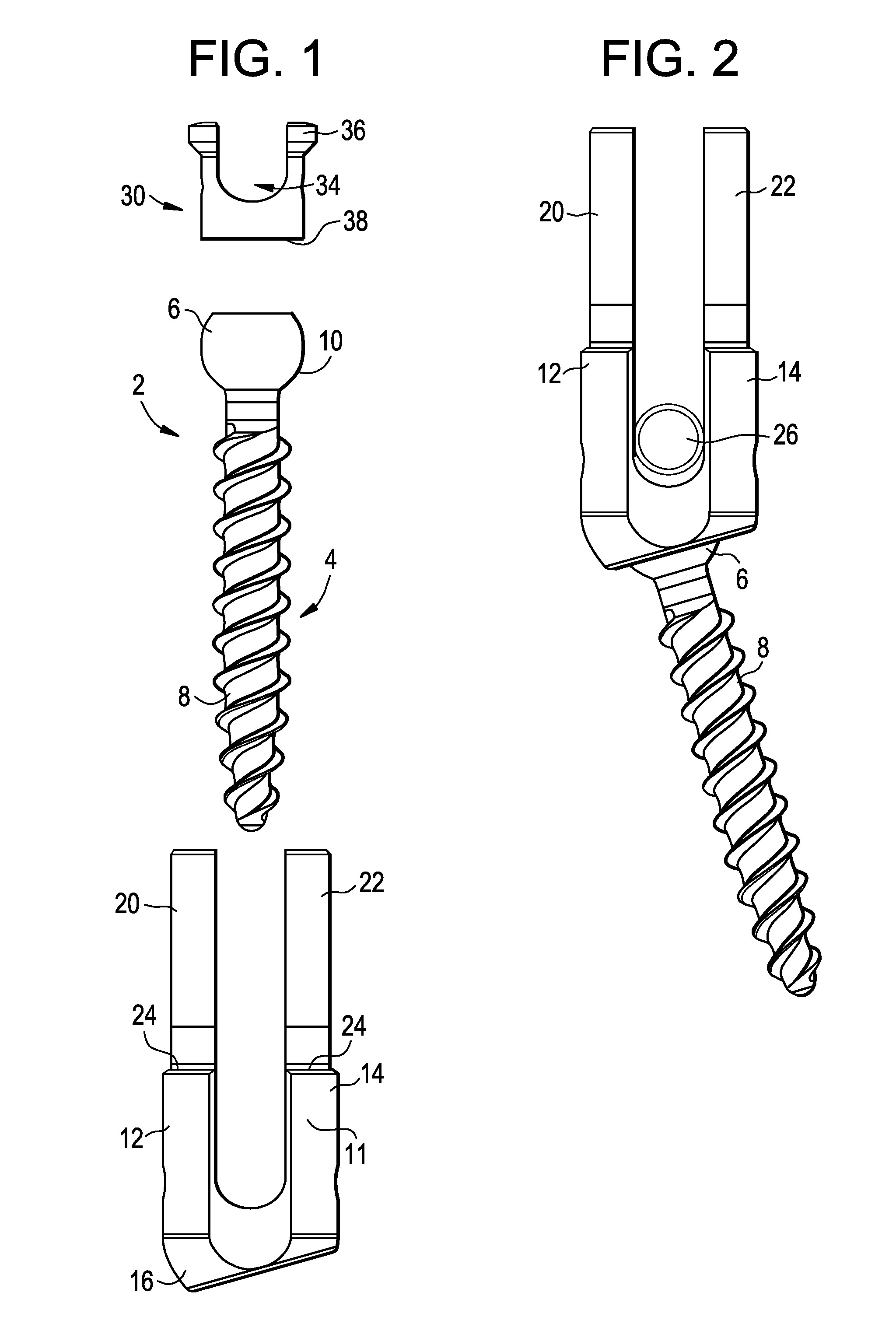
[0063]Referring to the drawings, FIGS. 1 and 2 show a fixation screw assembly 2 which can be used in the technique which is provided by the invention. The assembly comprises a fixation screw 4 which has a head 6 and a threaded shaft 8. The head 6 has a bearing surface 10 which forms part of a sphere. The head 6 has a socket formed in it which can receive the end of a driver tool to enable torsional forces to be applied to the screw to drive it into a bore in a patient's bone. It will often be preferred for the socket to have the shape of a regular polygonal, for example square or hexagonal. Other suitable sockets can be star shaped. The configuration of the thread on the shaft 8 will be selected according to the nature of the bone into which the screw assembly is to be fixed. The factors which affect the design of bone screws are well understood in the literature.

[0064]The assembly includes a channel 11 which comprises a pair of parallel arms 12, 14 and a base 16 which extends betwe...


PUM


Abstract

A method of treating a spinal column shape deformation includes fixing at least two fixation screw assemblies to respective vertebrae, sliding a rod between the arm extensions on each of the fixation screw assemblies, swinging the channels of the screw assemblies relative to the fixation screws so that the channels become less inclined to the axes of the fixation screws, and so that the rod is located generally posteriorly of the spinal column, locking the channel against swinging relative to the screw, rotating the rod about its axis relative to at least one of the channels, and locking the rod against movement relative to the channel.

Description

REFERENCE TO RELATED APPLICATIONS[0001]This application is a continuation of U.S. application Ser. No. 12 / 365,225, filed Feb. 4, 2009, which claims priority to U.S. Provisional Patent Application Ser. No. 61 / 026,048, filed Feb. 4, 2008, both of which are incorporated herein by reference.BACKGROUND[0002]This invention relates to spinal support rod kits and methods for the treatment of spinal column shape deformation.[0003]Support rods which are used to support a spinal column can be fastened to the patient's vertebrae by means of fastening devices such as for example by bone screws or hooks. The support rods can help to support the spine in a desired alignment. A support rod can define a shape towards which a deformed spine is to be corrected. Attaching the vertebrae to the rod causes vertebrae which are out of position to be drawn towards the rod, so that they can then be retained in a correct alignment against forces imposed by soft tissue tending to revert the configuration of the...

Claims


Application Information

Patent Timeline
IPC IPC(8): A61B17/70
CPCA61B17/7038A61B17/7002A61B17/88A61B17/7032
Inventor HUTCHINSON, JOHN
Owner DEPUY SYNTHES PROD INC
Why Eureka
Try Eureka