Three axis angle invariant RF coil assembly and method and system employing same

a three-axis angle, invariant technology, applied in the field of magnetic resonance imaging or spectroscopy systems, can solve problems such as even more acute limitations, and achieve the effect of equal effective capacitan

Inactive Publication Date: 2008-06-24
GENERAL ELECTRIC CO
View PDF6 Cites 20 Cited by
  • Summary
  • Abstract
  • Description
  • Claims
  • Application Information

AI Technical Summary

Benefits of technology

[0007]Briefly, in accordance with one embodiment of the invention, a radio frequency coil assembly for use in a magnetic resonance system comprises a set of conductors for detecting magnetic resonance signals in three orthogonal planes, where a conductor of the set of conductors is placed on each e

Problems solved by technology

One common limitation which exists while using these coils is that the B1 sensitive axis of the coil is generally kept in an orientation perpendicular to B0 magnetic field for maximum sensitivity and SNR.
In quadrature arrangements, another limitation is that

Method used


Image

  • Three axis angle invariant RF coil assembly and method and system employing same
  • Three axis angle invariant RF coil assembly and method and system employing same
  • Three axis angle invariant RF coil assembly and method and system employing same

Examples


Embodiment Construction

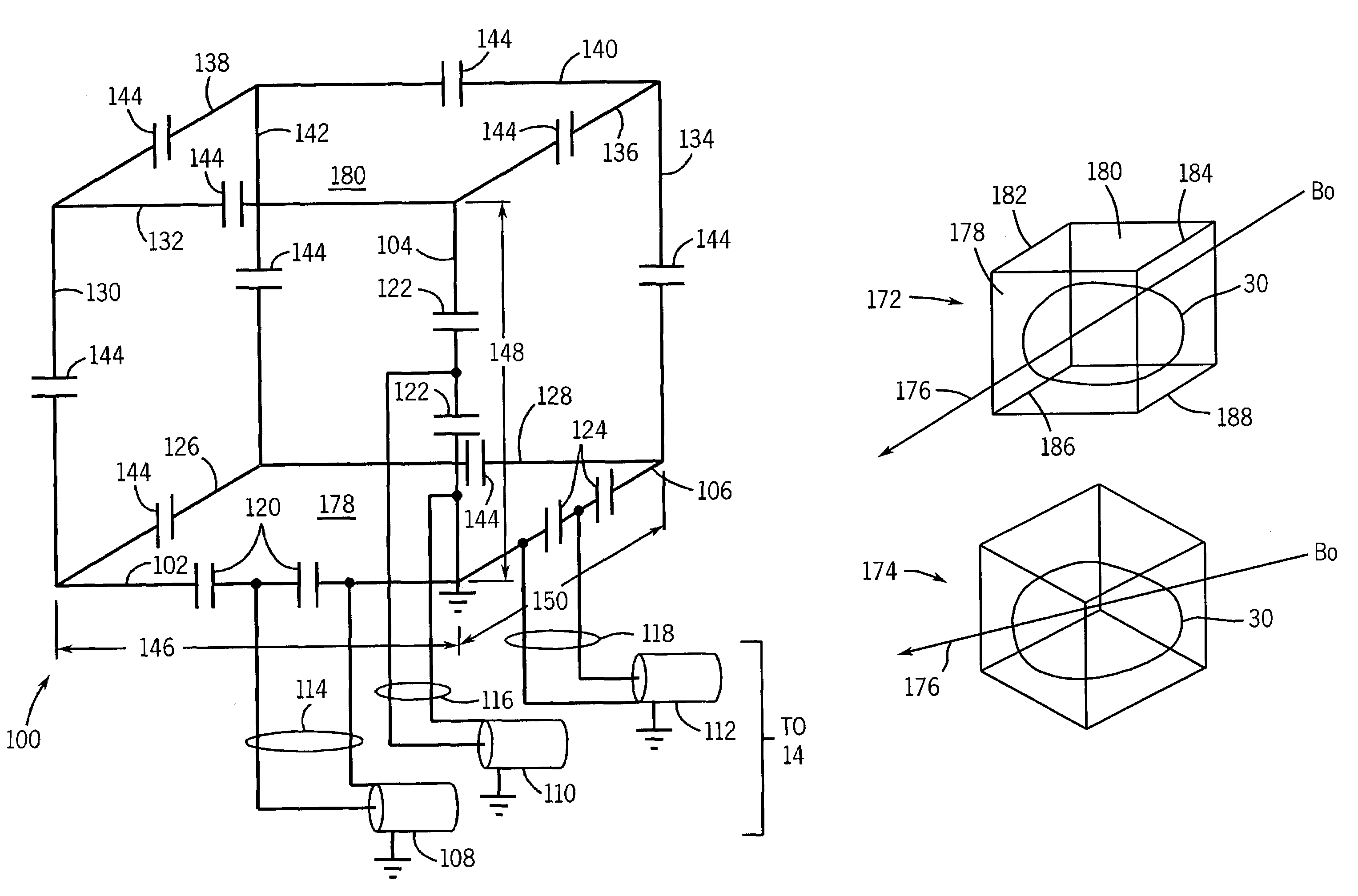
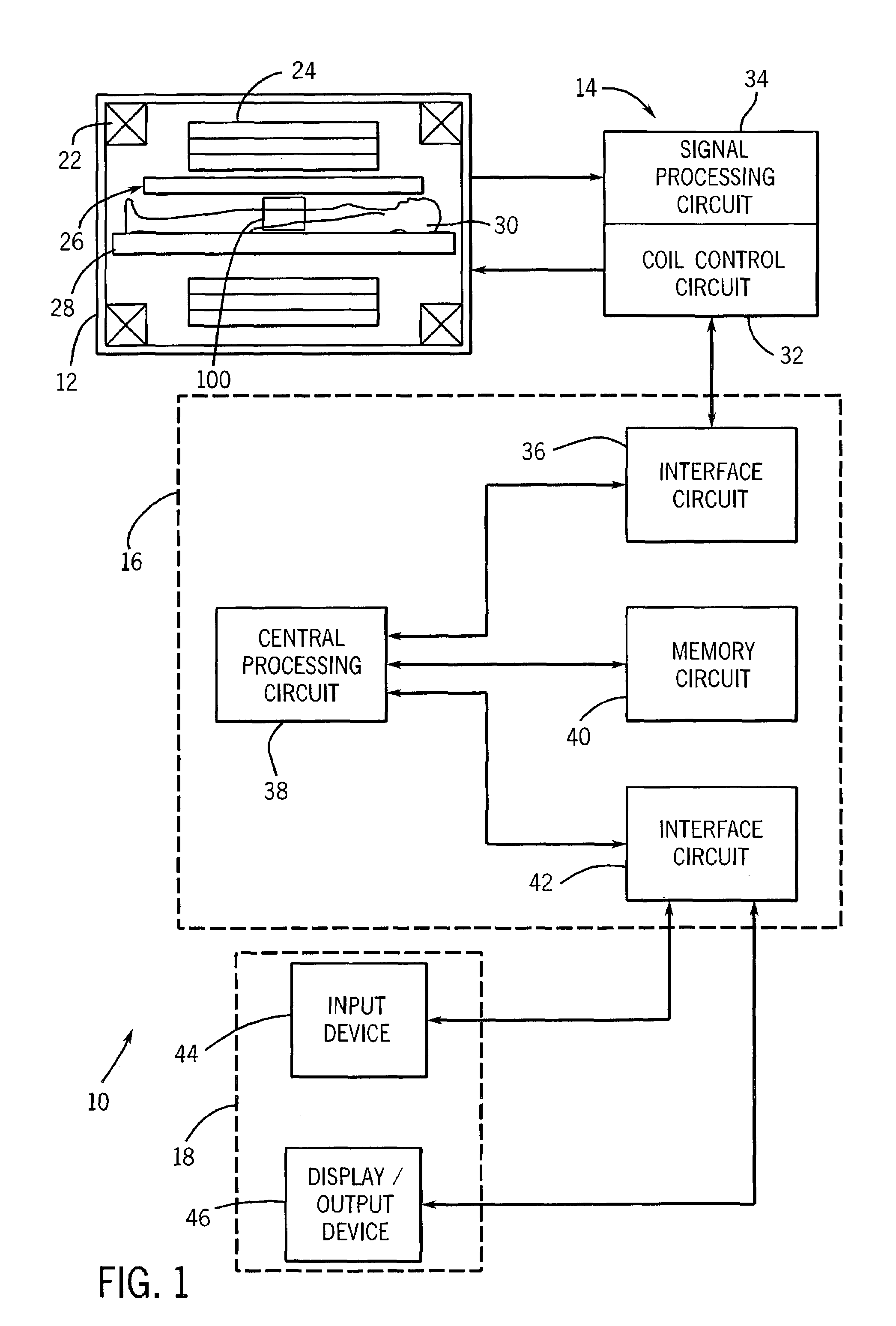
[0015]Referring now to FIG. 1, a magnetic resonance system, designated generally by the reference numeral 10, is illustrated as including a magnet assembly 12, control and acquisition circuit 14, system controller circuit 16, and an operator interface station 18. The magnet assembly 12, in turn, includes coil assemblies for selectively generating controlled magnetic fields used to excite gyromagnetic materials spin systems in a subject of interest. In particular, the magnet assembly 12 includes a primary coil 22, which will typically include a super conducting magnet coupled to a cryogenic refrigeration system (not shown). The primary coil 22 generates a highly uniform B0 magnetic field along a longitudinal axis of the magnet assembly. A gradient coil assembly 24 consisting of a series of gradient coils is also provided for generating controllable gradient magnetic fields having desired orientations with respect to the subject of interest. In particular, as will be appreciated by th...


PUM


Abstract

A radio frequency coil assembly for use in a magnetic resonance system comprises a set of conductors for detecting magnetic resonance signals in three orthogonal planes and capacitors for resonating the set of conductors at a predetermined frequency. A conductor of the set of conductors is placed on each edge of a cube-shaped volume and the capacitors are placed on each conductor of the set of conductors such that each conductor has substantially equal effective capacitance.
A four element band pass birdcage coil comprises two square end ring segments, each end ring segment comprising four sides of equal length, and four rungs of length equal to a side of the end ring segment, and wherein four rungs join in respective corners of the end ring segments.

Description

BACKGROUND OF THE INVENTION[0001]The invention relates generally to Magnetic Resonance Imaging (MRI) or Spectroscopy systems and more specifically to a radio frequency (RF) coil assembly for use in such systems, the coil assembly being invariant in its performance with respect to the angle and orientation of a main magnetic field of these systems.[0002]Magnetic Resonance Imaging (MRI) is a non-invasive imaging technique, in which the imaged subject is kept in a static main magnetic field, known as the B0 field and the nuclei of the imaged subject are excited by the radio-frequency (RF) magnetic field known as the B1 field. Magnetic Resonance Spectroscopy is a similar technique used to identify chemical makeup of a subject. For certain MRI and Spectroscopy systems, a plurality of radio frequency coils are needed to transmit the RF energy to the nuclear magnetic moments as well as to receive the extremely small signal that comes back from the subject. The signals, referred to as magne...

Claims


Application Information

Patent Timeline
IPC IPC(8): G01V3/00A61B5/055G01R33/34
CPCG01R33/34046G01R33/34092
Inventor WATKINS, RONALDDUMOULIN, CHARLESGIAQUINTO, RANDY
Owner GENERAL ELECTRIC CO
Why Eureka
Try Eureka