
Apparatus and method for selecting image to be displayed

Inactive Publication Date: 2008-06-24
SAMSUNG ELECTRONICS CO LTD
View PDF9 Cites 4 Cited by
  • Summary
  • Abstract
  • Description
  • Claims
  • Application Information

AI Technical Summary

Benefits of technology

[0008]To solve the above problems, it is one aspect of the present invention to provide an apparatus and method for selecting an image signal to be displayed, through which one of an image signal input from an image signal inputting device and an image signal obtained by changing the size of the image signal input from the image signal inputting device is selectively displayed on a display device.

Problems solved by technology

Thus, it is impossible for a user to reproduce images of various sizes using a general display apparatus.
Also, in a case where the size of an image input from a camera is very large, a bandwidth of a bus becomes exhausted.
However, when a system clock frequency is increased to solve this problem, high power consumption, which is highly undesirable in portable display apparatuses, is unavoidable.

Method used


Image

  • Apparatus and method for selecting image to be displayed
  • Apparatus and method for selecting image to be displayed
  • Apparatus and method for selecting image to be displayed

Examples


first embodiment

[0024]First, an apparatus for selecting an image signal to be displayed, according to the present invention, will be described with reference to FIGS. 1 and 7.

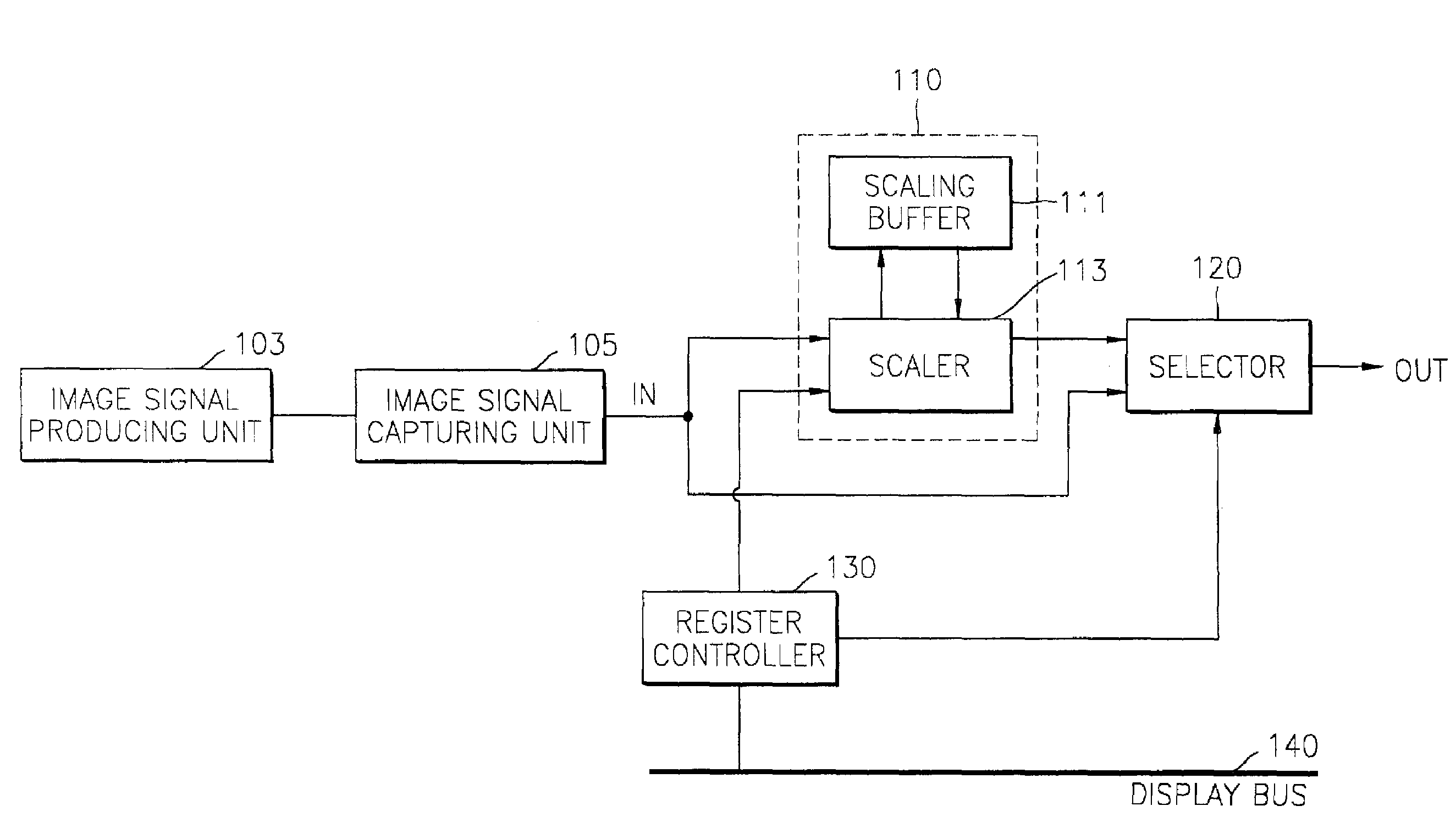
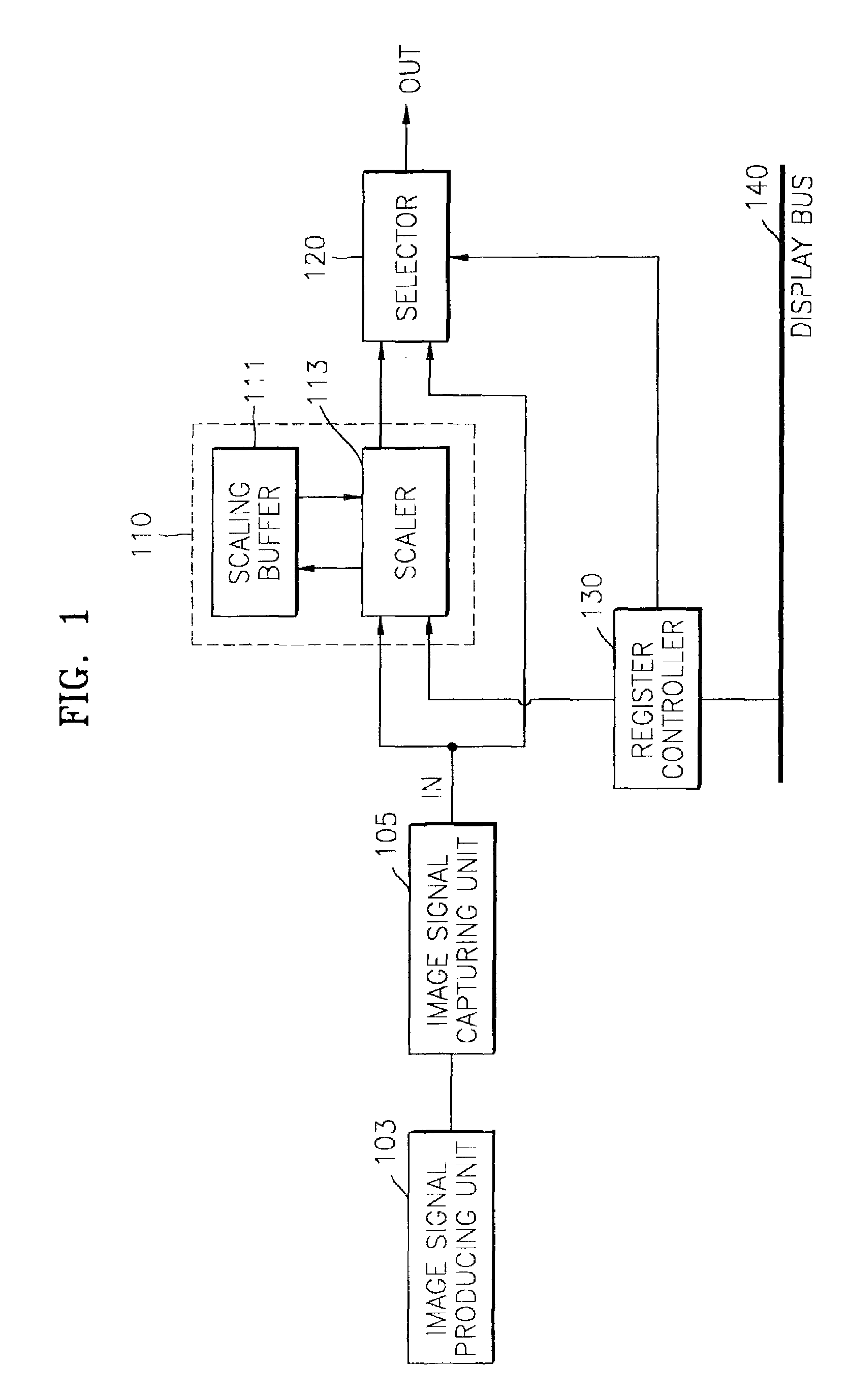
[0025]FIG. 1 is a block diagram of an apparatus for selecting an image signal to be displayed, according to a first embodiment of the present invention. Referring to FIG. 1, the apparatus includes an image size converter 110 for changing the size of an image signal, a selector 120, a register controller 130, and a display bus 140. The image size converter 110 includes a scaling buffer 111 and a scaler 113.

[0026]The image size converter 110 receives a first image signal that is input via an input terminal IN in units of frames. The first image signal is obtained by capturing an image signal generated by an image signal production unit 103, such as a charge-coupled device (CCD) camera, in units of frames. To capture an image signal generated by a CCD camera in units of frames, an additional image signal capturing unit 105 may be...

second embodiment

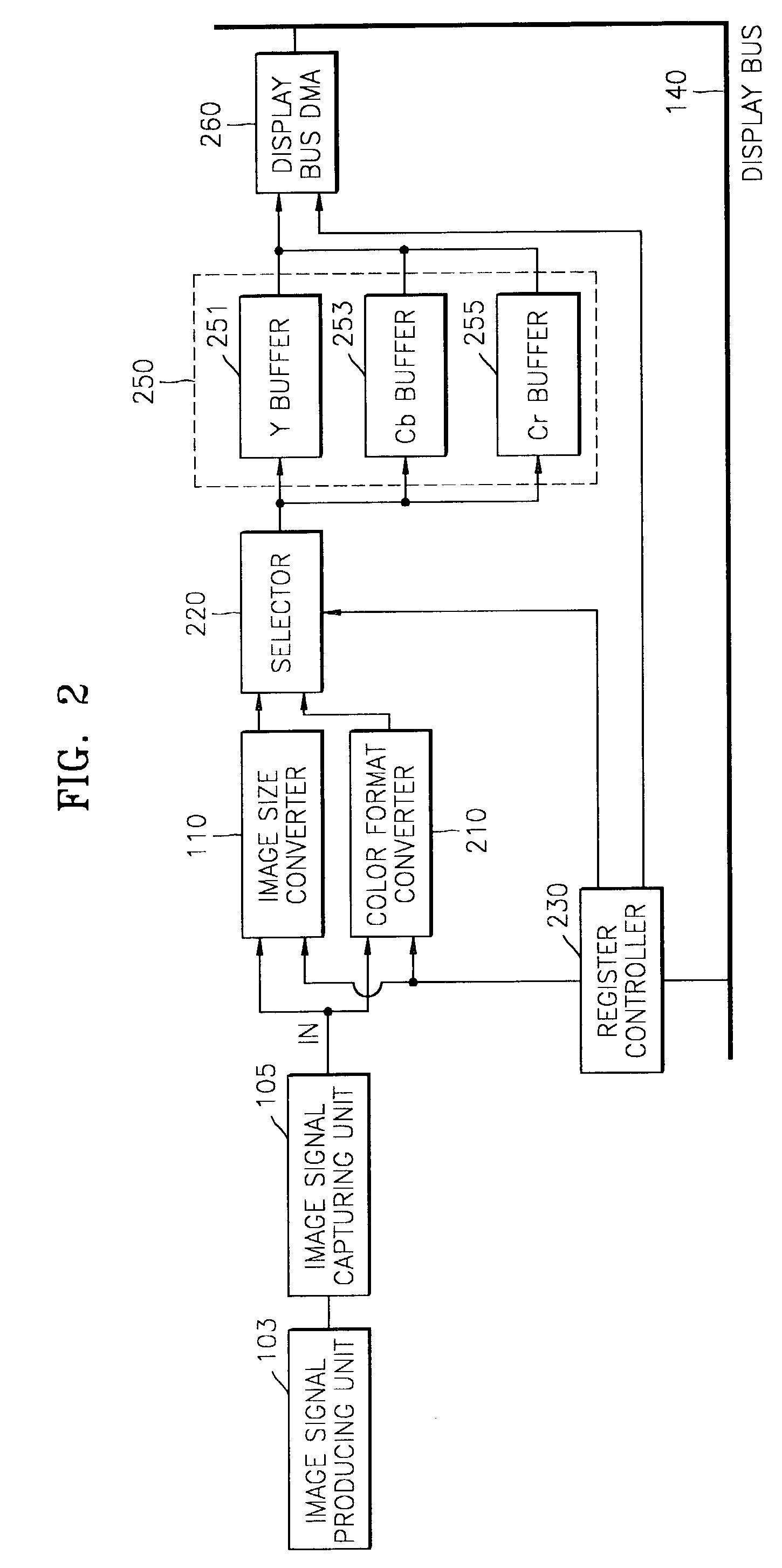
[0034]FIG. 2 is a block diagram of a selective image signal reproducing apparatus according to the present invention. The apparatus includes an image size converter 110 for changing the size of an image signal, a color format converter 210 for converting the format of a color signal, a selector 220, a register controller 230, a display bus buffer 250, a display bus direct memory access (DMA) unit 260, and a display bus 140. The display bus buffer 250 includes a Y buffer 251, a Cb buffer 253, and a Cr buffer 255.

[0035]Here, it is assumed, for convenience, that the size of an image signal input via an input terminal IN is 720×480, and a color signal has a format ratio of 4:2:2, as in the first embodiment. The image size converter 110 is the same as in the first embodiment described with reference to FIG. 1, and therefore, its description will be omitted here. Also, here, as explained with reference to FIG. 1, an image signal input via the input terminal IN and an image signal output f...


PUM


Abstract

Provided are an apparatus and method for selecting one of an image signal input from an image signal inputting device and an image signal obtained by changing the size of the image signal input from the image signal inputting device and displaying the selected image signal on a display device. The apparatus includes an image size converter for changing the size of a first image signal and outputting the result as a second image signal; and a selector for receiving the first and second image signals and selectively outputting one of the first and second image signals in response to a first control signal. With the apparatus and method, it is possible to selectively reproduce a high-definition image and a low-definition image.

Description

BACKGROUND OF THE INVENTION[0001]This application claims the priority of Korean Patent Application No. 2002-41582, filed Jul. 16, 2002 in the Korean Intellectual Property Office, which is incorporated herein in its entirety by reference.[0002]1. Field of the Invention[0003]The present invention relates to the field of image signal reproduction, and more particularly, to an apparatus and method for selecting an image to be displayed by which one of an image signal input from an image signal inputting device and an image signal obtained by rescaling the image signal input from the image signal inputting device is selectively displayed on a display device of a system that preprocesses input digital image data.[0004]2. Description of the Related Art[0005]Conventionally, in order to encode an image signal input from a camera to be transmitted to or stored in a certain device, a portable display apparatus having an image reproduction device, such as a PDA (personal digital assistant) or a...

Claims


Application Information

Patent Timeline
IPC IPC(8): G06K9/32G06F13/28H04N7/14G06F13/36G09G5/00G09G5/02G09G5/04
CPCG09G5/006G09G5/04G09G2340/02G09G2340/0407H04N7/14
Inventor JEON, JONG-GU
Owner SAMSUNG ELECTRONICS CO LTD
Features
  • Generate Ideas
  • Intellectual Property
  • Life Sciences
  • Materials
  • Tech Scout
  • Unparalleled Data Quality
  • Higher Quality Content
  • 60% Fewer Hallucinations
Learn More